In the world of flexible circuit boards, stiffeners are a common requirement in a lot of flex designs. By definition, a circuit board stiffener provides a mechanical support function and is not part of the electrical schematic of a design.
Paul Tome

Recent Posts
It is critical for any flex circuit design to be free of errors and violations in order to get the application to market as fast as possible without unnecessary delay. To help designers avoid common IPC PCB design standards violations in rigid-flex PCBs, this blog post will discuss three of the most common IPC Association Connecting Electronics Industries design violations.
One question we get asked frequently is: "Why does flex and rigid-flex PCB tooling cost more than rigid PCBs?" The answer is quite simple; flex circuit tooling is a much more complex process than standard printed circuit boards.
Previously, we gave you the definition for flexible circuit coverlay. Now, we go into greater depth discussing the two primary options for encapsulating the external circuit layers of a flex circuit: polyimide coverlay and flexible liquid photoimageable (LPI) solder mask. The two materials have very different capabilities and requirements.
Rigid-flex printed circuit boards are unique in terms of integrated construction of both rigid and flex circuit technologies. Unique construction comes with unique requirements that should be reviewed and implemented during the rigid-flex PCB Gerber layout phase of the design process.
Flex and rigid-flex PCB constructions have many variations that allow for a wide range of applications and solutions. A significant difference to rigid PCB constructions is that uneven layer counts are allowed and frequently used. The primary reasons being reduced flex thickness, improved flexibility and reduced part cost.
Essential to any flex or rigid-flex printed circuit board (PCB) contruction is validation that your flex PCB design will meet your mechanical bend requirements. Minimum flex bend radius requirements were put in place so your design won't exceed the physical capabilities of copper circuitry, which would result in failed parts, long term reliability concerns, and several giant headaches.
This blog post is intended to reinforce the design support we offer at Epec for our flex and rigid-flex PCBs. Technical design and engineering is one of our core foundations which allow us to best help our customers meet their product requirements. Within the post, we'll cover design areas that require special consideration.
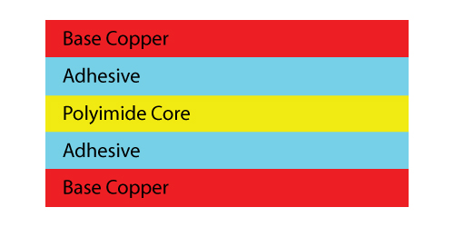
Two distinct types of polyimide flex core material constructions are utilized in today’s flex circuit manufacturing: adhesive based and adhesiveless. The difference, as you can probably tell from the name, is the method used to attach the copper layers to the polyimide core. This creates a unique set of material properties for each of the material types which must be factored into designs to meets all requirements and remain cost effective.
The copper weight and corresponding thickness used in a flexible circuit board need to be carefully selected in order to meet both the electrical and mechanical bend requirements of specific flex circuit design. Copper weight for a flex PCB is both the stiffest and most critical component.


