



Military and aerospace systems operate in some of the harshest environments imaginable. Whether installed on a military ground vehicle, commercial aircraft, unmanned aerial system, naval vessel, or satellite subsystem, cable assemblies are routinely exposed to vibration, shock, temperature extremes, moisture, harsh chemicals, and electromagnetic interference. In these applications, reliability is not simply desirable, it is essential.
A single cable failure can disable critical communications, interrupt power distribution, compromise navigation systems, or take an entire platform out of service. Because of this, military and aerospace cable assemblies require specialized materials, assembly techniques, testing procedures, and quality standards that go well beyond those used in conventional commercial products.
Common Cable Assemblies Used in Military and Aerospace Applications
Military and aerospace platforms rely on a wide variety of cable types depending on the application. Data, signal, and power cables constructed from stranded copper conductors remain among the most common. These cables support everything from avionics and instrumentation to power distribution and communication systems.
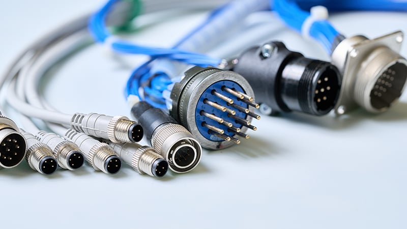
Example of common cable assemblies used in military and aerospace applications.
Coaxial cables are also heavily utilized for RF communication systems, radar equipment, antennas, and high-frequency signal transmission. These assemblies must maintain precise electrical characteristics while surviving challenging performance requirements and environmental conditions.
Many applications require high-performance cable constructions able to operate in extreme temperatures. Aircraft missions at high altitudes and military equipment deployed in desert or arctic environments may experience temperatures far outside the operating range of conventional commercial cable materials. For example, an aircraft sitting for hours on a hot tarmac experiences one set of temperature extremes, and within minutes that same aircraft may be cruising at 40,000 feet with completely different cold temperature extremes.
To support these demanding conditions, manufacturers often incorporate specialty sleeving, braiding, jacketing materials, and shielding systems designed specifically for harsh environments. EMI and EMC-resistant components are frequently required to protect sensitive electronics from interference while ensuring compliance with military and aerospace performance requirements.
Common Military and Aerospace Wire and Connector Systems
Many aerospace and defense cable assemblies are built using proven military-specification wire and connector systems that have been qualified for demanding applications.

Among the most common wire specifications are M16878/1, M22759, and M27500. These are some of the wire types that cover a broad range of conductor constructions, insulation materials, temperature ratings, and environmental requirements. They are widely used throughout aircraft, defense electronics, and mission-critical systems.
On the connector side, MIL-DTL-38999 circular connectors are among the most specified interconnect systems in the industry. These rugged circular connectors provide excellent environmental sealing, vibration resistance, and high-density contact arrangements. Most importantly, within the 38999 family of connectors, there are dozens of variations for pin count and attachment methods, including panel-mount and right-angle configurations.
Most of these connector systems utilize soldered contacts that are installed into environmentally sealed connector grommets. The resulting assembly provides both excellent electrical performance and strong environmental protection. Crimped terminals are also common but may require specialty tooling and assembly techniques to install properly.
Shielding is another major consideration. Military and aerospace cable assemblies often incorporate multiple shielding layers consisting of wrapped conductive films, braided tinned copper shields, and metallic overbraids. These shielding systems help protect against electromagnetic interference while maintaining signal integrity.
Additional materials such as lacing tape, PTFE films, Kapton tape, mil-spec heat shrink tubing, potting compounds, and encapsulation materials are frequently incorporated to further improve durability and environmental resistance.
Following Proven Industry Standards
One of the most effective ways to improve reliability is to build assemblies in accordance with IPC/WHMA-A-620, commonly referred to as IPC-620. This standard establishes workmanship requirements, inspection criteria, and acceptance standards for cable and wire harness assemblies. It provides clear guidance regarding soldering, crimping, splicing, insulation preparation, wire routing, strain relief, testing, and overall assembly quality.
Following IPC-620 helps ensure consistency across production runs and reduces the risk of workmanship-related failures. It also provides a common language between customers, manufacturers, inspectors, and quality teams.
For military and aerospace applications, IPC-620 should be viewed as the foundation rather than the finish line. Many programs impose additional customer-specific requirements that exceed the baseline standard. The OEM and/or the Department of Defense have the final say in all assembly and workmanship criteria.
Selecting High-Performance Assembly Materials
The cable itself is only one part of the overall system. Connector accessories and assembly materials often determine whether a cable survives years of service or fails prematurely.
High-performance backshells, strain relief devices, connector hardware, banding materials, and specialized tooling all contribute to long-term reliability. Using the correct assembly tools is especially important because improper crimping, soldering, or termination techniques can introduce hidden defects that may not appear until the assembly is in service.
Additional materials such as fiberglass cloth tapes, specialty films, high-temperature shrink boots, and protective wraps can provide additional mechanical support while improving resistance to heat, abrasion, and environmental exposure.
Cable Bundling Techniques to Improve Ruggedization
Many military and aerospace harnesses are not built from a single multiconductor cable. Instead, they are often assembled from numerous individual conductors or smaller cable legs that must be bundled together in a specific configuration.
The way these conductors are bundled has a direct impact on flexibility, durability, bundle diameter, and overall performance.
One common technique is known as unilay construction. In a unilay configuration, all conductors are twisted in the same direction throughout the cable bundle. This method is relatively simple to manufacture and is often used in static installations where the cable experiences little movement after installation.
For applications requiring continuous movement or repeated flexing, a contra-helical lay configuration is often preferred. In this construction, each layer of conductors is wrapped in the opposite direction from the previous layer. This alternating pattern helps distribute mechanical stresses more evenly throughout the cable, improving flexibility and extending service life in dynamic applications.
The Importance of Proper Strain Relief
If there is one area that deserves special attention in any military or aerospace cable assembly, it is strain relief. The most vulnerable location in a cable assembly is often the transition point between the cable and the connector. Without adequate strain relief, vibration, movement, and handling forces are transferred directly to the electrical terminations or create stress concentration on the wire itself.
This can create intermittent connections, exposed conductors, and short circuits, which can damage other parts of the system. Proper strain relief significantly reduces the risk of conductor breakage, solder joint failures, and connector damage over the life of the assembly.
Specialized backshells are commonly used to provide mechanical support and secure the cable to the connector body. Potting compounds, RTV materials, shrink boots, and sealing systems further reinforce this area while providing environmental protection.
Understanding Clocking Orientation
High-conductor-count cable assemblies often require precise clocking orientation to ensure proper installation and routing.
Clocking orientation refers to the rotational alignment of one connector relative to another connector within the same cable assembly. The goal is to position connector keyways at specific angles so the cable naturally routes through the equipment without twisting or placing unnecessary stress on the conductors.
Fixtures, pegboards, and custom assembly tooling are commonly used to maintain proper orientation during manufacturing. Typical clocking tolerances are often maintained within ±15 degrees, although some applications may require tighter controls.
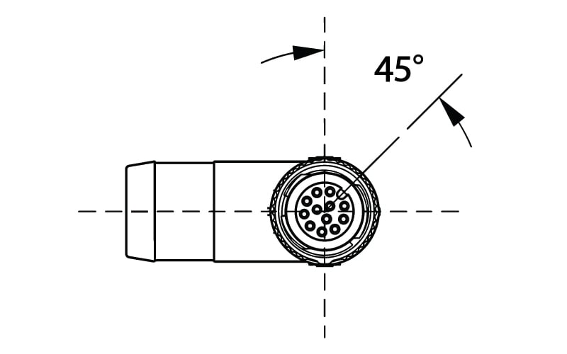
Clocking orientation example.
Electrical Testing Is Essential
Even the highest-quality assembly materials and workmanship are ineffective if defects go undetected.
Continuity testing remains one of the most fundamental electrical verification methods, ensuring every conductor is terminated correctly. Dielectric withstand testing, often called hipot testing, verifies insulation integrity and confirms there are no unintended leakage paths between conductors.
For military and aerospace assemblies, in-process testing is highly recommended. Performing continuity and hipot testing before RTV, potting compounds, or encapsulation materials are applied allows manufacturers to identify and correct issues early. Finding a wiring error after the assembly has been fully potted can turn a simple repair into a costly rework project.
Using automated electrical test setups and testers is another way to help reduce the complexity and challenges with some of the more sophisticated tests necessary. For hipot testing, each conductor must be tested against all adjacent pins and wires, and because of all the combinations, this test can result in hundreds or thousands of discrete hipot tests being performed on one cable. For a simple cable with one or two legs, this is not a concern; however, for high-density connectors with dozens or hundreds of pins, using an automated tester is the only option to perform these tests.
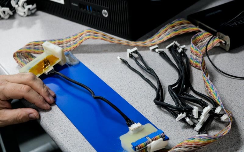
Cable assembly electrical test.
Summary
Ruggedizing cable assemblies for military and aerospace applications require much more than selecting a durable connector or specifying a high-temperature wire. Long-term reliability is achieved through a combination of proper materials, proven assembly methods, robust strain relief, precise clocking orientation, disciplined testing procedures, and adherence to industry standards.
When every connection matters and failure is not an option, investing in the right design and manufacturing practices from the beginning can make all the difference in the performance and longevity of the final system.
Key Takeaways
- Military and aerospace cable assemblies rely on specialized materials, shielding systems, connectors, and construction methods designed to withstand extreme temperatures, vibration, moisture, and electromagnetic interference.
- Common military-specification wire types such as M16878/1, M22759, and M27500, along with MIL-DTL-38999 circular connectors, form the foundation of many high-reliability aerospace and defense interconnect systems.
- Proper bundling techniques matter. Unilay constructions are typically used for static applications, while contra-helical lay constructions provide improved flexibility and durability for continuous flex applications.
- Effective strain relief using backshells, potting compounds, RTV materials, and sealing boots is critical because the cable-to-connector interface is often the most vulnerable area of the assembly.
- In-process electrical testing, including continuity and hipot testing before potting or encapsulation, helps identify defects early and prevents costly rework while improving overall assembly reliability.