


An electrical continuity test is used to determine if there is an uninterrupted path within a circuit allowing current to pass. Continuity allows electrical components to become properly energized and operate as intended. Simple electrical tests can help verify continuity quickly and inexpensively in a circuit, with sophisticated test equipment available for higher complexity options.
In the case of a cable assembly, detecting electrical continuity is a relatively straightforward test. If there is a problem, issues such as high electrical resistance may create an open circuit, or, damaged connectors and wires may be accidentally cut, creating an open circuit. Performing electrical continuity testing helps spot these malfunctions and helps engineers remedy the problem. This is especially important for custom cable assembly manufacturers since delivering high-reliability electrical products are a critical business requirement.

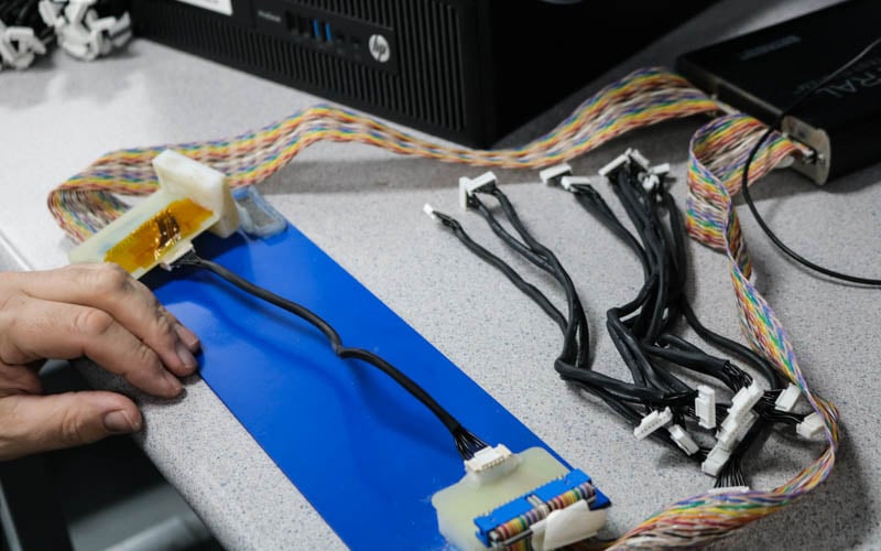
Customized continuity test setup for a multiconductor cable assembly.
Why Perform Continuity Testing on Cable Assemblies?
Cable assemblies should have a closed circuit when in operation. A closed-circuit indicates that the electrical current or signal moves from one point of the cable assembly to the desired endpoint. If the electrical current fails to flow, it could indicate that there is a problem that you should address. There are several reasons that a custom cable manufacturer performs a continuity test.
Flagging Open Circuits
A circuit path runs from one end of the cable to the other end. When a cable is connected between a power or data source, it is called a closed circuit. Electrical current can now pass as intended between the sources uninterrupted.
A continuity test checks to see if there are any open circuits, which are not complete circuits and would show on a multimeter as an “open loop”. A common open circuit issue would be a break in a wire or making a wrong connection between the cable assembly and one of its connections.
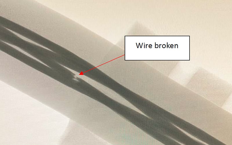
Broken wire creating an open circuit are visible using x-ray technology.
Verifying Pin-Out
Pin-out refers to the connection of each wire within a multiconductor cable. A pin-out identifies every individual pin and where it should be electrically connected.
A continuity test checks to ensure that the cable assembly and pin are connected correctly. The test scouts for mis-wirings and can help identify crossed wires. Connectors that are accidentally crossed can damage the circuit or other system components. Verifying the pin-out ensures that the cable assembly operates as designed.
Electrical Continuity Testing Equipment
Manufacturers test electrical continuity through cables using a wide range of equipment. Some equipment may consist of benchtop devices, handheld devices, and custom setups when testing the functions of specialty cable assemblies. Here are several types of electrical continuity testing equipment:
- Digital multimeter: A digital multimeter has a large dial and two probes, along with other functions based on the manufacturer. A worker sets the dial to what will be tested with the cable assembly, such as voltage, resistance, continuity, and other factors. The test sends a small current through the ends of the probes and will give an audible sound or visual cue to indicate a closed circuit.
- Ohmmeter: An Ohmmeter device only checks the resistance between two points. It looks and functions in a similar matter at a multimeter by giving off a small amount of current through the test leads and measures the resistance in the cables as “ohms”.
- Customized Test Setups: Some test engineers may use custom setups that consist of test leads and a power source to transmit current through the leads. These setups could come with buzzers, LEDs, lights, or other annunciator types that are designed to alert the engineer that the cable assembly provides electrical continuity.
Intermittent Electrical Continuity
Electrical continuity is binary, and a circuit is either OPEN or CLOSED. However, because of anomalies such as corrosion or a poor fitting connector, the circuit may go through periods where it works, followed by periods when the circuit does not work. Flexing the cable may exacerbate the issue or cause it to fix itself. While intermittent connections are somewhat random, they are generally caused by corrosion or stress on the cable.
Some electrical test systems are designed to help detect intermittent connectors and will trigger an event log if detected.
Other Electrical Tests for Cables
In addition to assessing the continuity of cable assemblies, engineers may also test other factors, such as the performance and reliability of custom cables and wire harnesses. These tests may consist of the following:
- Hipot/Dielectric Withstanding Voltage Test: A Hipot test applies a high voltage across two locations within a cable assembly and verifies there is no leakage current.
- Insulation Resistance Test: This test checks the electrical resistance of the insulation to determine the total amount of resistance between the two points along the cable assembly.
- Shielding/Braid Resistance Test: Cables have shielding that is used to stop signals from being transmitted from the cable assembly to other nearby cables. Measuring resistance values can help identify breakdowns in the shielding effectiveness.
Automatic Test Equipment
Some cable assemblies are complex with multiple wires and high pin counts designed to connect to large equipment systems. Evaluating each individual wire and connector manually and performing one test measurement at a time becomes a time-consuming and costly task.
Automated and computerized test equipment allows manufacturers to perform multiple types of measurements using one system. These measurements are tracked and monitored directly through connected software interfaces so the engineers can easily view collected information. Automatic test equipment is ideal for cable assemblies that have high pin counts.
Data Acquisition System (DAQ)
Data acquisition systems (DAQ) consist of hardware and software components to perform complex electrical measurements, usually over periods of time. Performing multiple measurements of cable assemblies sometimes leads to a large amount of data being available. This allows engineers to customize the types of measurements to be performed and what measurement data is captured by the system. This data is then recorded over a specific length of time.
A DAQ system offers a unique and simple way to post-process data, such as voltage, temperature, pressure, or current measurements for current and future use.
Summary
Measuring continuity is standard on nearly all custom cable assembly builds. But there are instances where a higher complexity test is necessary to satisfy program objectives. Continuity is usually sufficient, but for specialized cable assemblies that need additional testing, for both electrical and mechanical, systems engineers need to carefully define all performance requirements. Early engagement with a full-service electronics manufacturer such as Epec can help reduce costs and maintain schedules.
Key Takeaways
- Continuity testing is foundational, but not always sufficient: While continuity testing confirms closed circuits and proper pin-outs, it may not catch issues like intermittent faults, high resistance, or shielding breakdowns that can impact cable performance in real-world conditions.
- Open circuits and miswirings are common defects caught early: Continuity tests are essential for identifying broken conductors, improper pin-outs, or wiring mistakes during assembly that can damage equipment or compromise signal integrity.
- Advanced test methods assess performance and safety: Additional electrical tests like Hipot, insulation resistance, and shielding resistance are often needed to verify voltage isolation, insulation integrity, and EMI shielding, especially in high-reliability or high-voltage environments.
- Automated test systems improve efficiency for complex assemblies: Cable assemblies with high pin counts or large volumes benefit from automated test equipment and DAQ systems, which streamline testing, reduce labor time, and enhance traceability.
- Intermittent failures require special detection tools: Intermittent issues caused by corrosion, connector wear, or mechanical stress are difficult to catch with basic continuity checks. Specialized systems with event logging are required to reliably detect and troubleshoot these failures.


