


Custom cable assemblies are used everywhere in a variety of applications, supporting a diverse customer base. These custom cable assemblies may transmit power, data, or other high-fidelity signals during their operation, and in some applications may be used for life-saving or mission critical equipment. These cables must be reliable enough to continuously transmit signals without failure, and be strong enough to withstand certain mechanical stresses, and durable enough to withstand the environment they will operate within.
During development, products are typically subjected to a series of rigorous electrical, mechanical, and environmental tests, sometimes called qualification or verification and validation testing. These tests are intended to demonstrate that the overall product design meets the end application’s critical design requirements. Assuming that qualification testing results in an “all pass,” manufacturing is launched. Depending on the end application requirements, in process or final testing may be required. Knowing what tests are required (if any), when they are required to be performed, and what the “pass/fail” criteria are, must be reviewed before launching any custom cable assembly build.
Since some of these tests can impact cost and manufacturing time, understanding these test requirements and how the tests are performed will help improve your time to market and decrease your redesign risk.

What Tests are Required?
Since the primary job of a cable assembly is to electrically connect two devices, a simple test like electrical continuity is standard and performed on nearly all custom cables to demonstrate that it is operational. But there are several additional tests that may be required depending on the use case and end customer. Typically, if the cable will be used in a medical devices or mil-aero application, there will be additional tests required above and beyond electrical continuity. It is always best to refer these types of questions to your end customer should there be any doubt regarding the test requirements.
When are the Tests Performed?
Usually occurring at final inspection, most tests are performed at the completion of the manufacturing process and are intended to show that the cable assembly was fabricated correctly. These tests can be performed on 100% of cables built, or at a predefined acceptance quality limit (AQL) quantity. Other tests may be performed in-process to demonstrate that a specific manufacturing step was completed. For example, it’s a good idea to perform all required hipot tests before warming the heat-shrink to the recovered diameter, especially on a complex cable harness. This way the cable can be troubleshot and repaired easier.
Time is money, so the more tests that are required and the more often they are performed, the higher the overall cost to manufacture your custom cable harness. In addition, some tests will require specialty equipment, fixtures, and test apparatus. Furthermore, some tests are destructive and may damage the cable assembly, so it’s always best to review all program details before committing to a test sequence.
Electrical Testing Requirements
There are several tests that can be performed to ensure the electrical properties of the cable assembly meet all design requirements. Three common tests are:
- Electrical continuity test
- High potential/high voltage test (hipot)
- A milliohm test
These are a select group of tests that will prove the wiring is correctly assembled, that there are no open circuits, and that the cable assembly does not have internal shorts or intermittent connections. Another consideration is that for some of these electrical tests, the mating connectors must be sourced and assembled into the test apparatus. This is important because some specialty connectors have extremely long lead times, sometime in excess of 16 weeks.
Electrical Continuity Test
This test confirms that the connectors and wire are properly assembled by verifying that current flows through the cable. This test will measure the circuit’s resistance, and measure whether there is an electrical connection between the test points. Should there be any damaged conductors or broken wires, the continuity test will reveal an open circuit. A high resistance measurement indicates that there is an improper connection within the assembly that is at risk of failing.
To test for electrical continuity, two or more test points will be connected to a multimeter device that is set to measure resistance (Ω) or continuity. The multimeter will send a small voltage between the test points and measure the overall circuits resistance. Some multimeters annunciate if there is electrical continuity via an audible beep. If there is an open circuit, the multimeter usually displays the corresponding open loop message.
Through the use of automated test equipment and the appropriate test fixtures, all legs on a multi-conductor cables can be tested at once, instead of manually testing each individual conductor set. This automated test equipment is highly specialized and must be customized for each specific cable configuration.
Hipot Test
This test, also called the dielectric strength test, will evaluate the insulation jacket within the cable for defects, gaps, or any contamination. The test will check to see if there is any current leakage or if there are any internal short circuits.
A high voltage, sometimes in excess of 10kV, will be passed across two conductors to induce a significant amount of stress on the electrical insulation and soldered connections. If the circuit withstands the high voltage during the short-specified timeframe, it will be an indication that the cable assembly will be safe to use with nominal voltage output during the lifespan of the product or application.
For multiconductor cable assemblies, the HIPOT test typically tests all adjacent conductors. This is important because for a cable with only a few conductors, this test can be done quickly with a simple HIPOT test machine. However, for a +20 conductor cable, this could require hundreds or thousands of individual HIPOT measurements to thoroughly test all conductor combinations. There are specialty test equipment manufacturers that make automated HIPOT test equipment, but these can cost thousands of dollars to procure. As always, it’s best to understand how the tests are performed before requiring that you supplier adhere to them.
Milliohm Test
A milliohm resistance test is used to measure extremely low resistance connections in cable assemblies. The goal of the test is to determine the condition and quality of the electrical connection and make sure it is within a predetermined range of acceptable values. One of the most common reasons to require a milliohm test is to verify that resistance of the ground circuit. Ideally the measured resistance between your cable and ground should be extremely low, but the typical multimeter style devices are not accurate enough to measure such low resistance values. These tests measure in the milliohm range as the name would imply.
A milliohm meter is used to perform the test and requires at 4-terminal measurement method where a current is applied to a portion of the cable assembly. Two of the terminals are used to measure the voltage, the two other terminals are used for current sensing. A common electrical bonding requirement is that this test measures 2.5 milliohms of resistance between two ground points. If the resistance is measure higher than 2.5 milliohms, the cable is rejected and must be evaluated.
Mechanical Testing Requirements
In addition to electrical testing, mechanical testing can be performed to evaluate the strength and cable assembly’s resilience to fatigue. The cables will be put through a variety of stress tests that include checking for elongation, impact resistance, crush resistance and tensile strength. Two basic tests that can be performed include a pull test and a flex/bend test.
Pull Test
A pull test is used to determine the strength of the wire, connectors, and crimp joints. The cable assembly will be pulled at a specified load and rate based on the type of wires and connectors that were used. Typically, a motorized pull tester will be connected to the wires as a pulling force is applied. Then, the tester will measure the amount of force used. For example, some customers require verification that the cable will withstand 40 pounds of force in tension with no damage being observed after the test is performed.
There can be several methods employed during the pull test, such as:
- Pull and break: this destructive test will apply a constant pull force until the wire or terminal breaks.
- Pull, hold, and break: this is another destructive measure where a pulling force is applied and held at a specified rate. Then the pulling force is increased by increments until the wire or connectors fail.
- Pull and hold: this is a non-destructive test where a pulling force is applied and then held at a specific rate for a certain length of time.
- Pull and release: as another non-destructive test, the cable assembly will be pulled at a specific rate and then the pulling force is removed.
The equipment required to test this can range from a fully automated test station capable of data acquisition and several configurations, to a simple weight being attached to the end of the cable and suspended for a predetermined amount of time.
A flex/bend test is used to assess the cable's durability to bending fatigue.
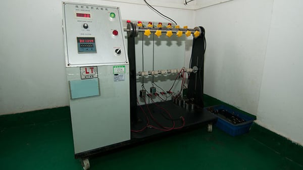
Flex/Bend Test
For many applications, the cable assembly will be routed, bent, flexed, and much more during its installation and throughout its useful life. If required by the end application, the cable assembly should move in any direction without the transmitted signals, power becoming disrupted, or damage to the jacket and insulation. Ideally, the custom cable assembly must be designed for continuous operation through cyclic bending and twisting. To evaluate this critical design concern, a flex or bend test is used to assess the cable's durability to bending fatigue.
A bend/flex machine is typically used where the cable is attached by one end. Then, the other end may be tied into a pretzel shape or have a weight attached to the other end as it bends the cable to a 90-degree angle. The cable may also undergo a rolling bend test where the other end is attached to a swing-arm mechanism that constantly flexes the cable as it swings back and forth at a 180-degree arc. Typically, a minimum bend radius and number of cycles must be defined in order to properly perform this test.
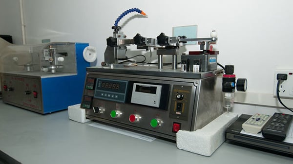
A pull test determines the strength of the wire, connectors, and crimp joints.
Environmental Testing Requirements
Cable assemblies will be used in a variety of indoor and outdoor environments. They may be subjected to extreme temperatures, high humidity, and even submersion, condensation, saltwater spray, or salt fog. Cables used in these conditions will need to demonstrate their resilience to these different environments, otherwise they are at risk of exhibiting premature aging, accelerated corrosion, or degradation of the electrical conductors and jacket. Typically, an end customer requirement, some applications demand compliance to a product safety specification or other national standard like IP67.
Listed below are some of the environmental tests that should be considered for your custom cable assembly:
- High/Low Temperature Storage
- Thermal Shock/Cycling
- Waterproofness
- Vibration
- Humidity
- Chemical and Fluids Exposure
- Salt Spray
- Fungus Exposure
Often, manufacturers can perform these tests in-house, while other more specialized tests must be subcontracted to a third-party test lab. This is important because if cost or schedule is critical, these tests are typically expensive and can have long lead times associated as you wait for chamber availability.
IP66/IP67 Water Ingress Protection Codes
When designers develop cable assembly specifications, they will refer to the International Electrotechnical Commission (IEC) when considering the protection rating that a cable will need when used in different applications and environments. IEC has classified these protection ratings under their International Protection (IP) code standards. IP may also refer to "Ingress Protection."
Each IP code will consist of two numbers. The first number will indicate the rate of protection from solid matter, such as dust and dirt. The second number will indicate the rate of protection against liquid substances, such as water. Basically, the cable assembly will have this code to indicate the level of protection it has. Two common ratings for a cable assembly are IP66 and IP67.
Typically, manufacturers will not provide the formal IPXX rating certification, rather they will design the cable and manufacturing process to meet these conditions. This testing can also be done in house by many cable assembly manufacturers, but the official approval must come from a properly recognized third-party lab.
- IP66 Rating: An IP66 rating for the cable assembly will mean that the wires and connectors are totally protected from dust, which is indicated by the first “6” in the code. The second “6” indicates that the cable assembly is protected from water ingress from high-powered water jets from any angle.
- IP67 Rating: An IP67 rating also indicates that the cable assembly is protected completely from dust, as is indicated by the first number in the code. The number “7” for the water ingress rating shows that the cable assembly is protected from moisture and water ingress when the wires are submerged to a depth of 15 cm up to 1 m and is held there for 30 minutes.
Fungal Resilience Test
Fungal growth in cable assemblies can occur in warm humid conditions on a variety of materials. This is especially true in marine applications where cable assemblies may be exposed to prolonged periods of darkness and moisture. When fungus begins to grow and spread, it can cause corrosion, premature aging, and other damage to the cable jacket, connectors, and conductors. One of the more common fungus test standards is per MIL-STD-810, a United States military standard used to demonstrate if a material or product is resistant to fungal growth.
The test consists of spraying a material coupon with fungus spores. The coupons are then placed into a chamber that is climate controlled, typically warm and humid to promote fungal growth. The coupons will then be monitored to determine if there is spore growth and to measure the rate of growth.
Custom Cable Assemblies Built for Your Application
Here at Epec, we help customers with their products and applications by selecting the right materials that have been strenuously tested. With our dedicated team of engineers, you will be rest assured that the cable assemblies will meet all electrical, mechanical and environmental protection standards when put into use.
Key Takeaways
- Testing Is Application-Driven: Basic continuity testing is standard, but medical, military, or mission-critical applications often require more rigorous electrical, mechanical, and environmental tests.
- Multiple Test Types Ensure Reliability: Common tests include electrical continuity, hipot (dielectric strength), milliohm (low-resistance bonding), mechanical pull and flex/bend tests, and environmental evaluations like thermal shock, vibration, salt spray, and IP66/IP67 ingress protection.
- Testing Impacts Cost and Lead Time: More tests, especially those needing specialized equipment or third-party labs (e.g., IP certification or fungal testing), can significantly increase manufacturing cost and production time.
- IP Ratings Provide Environmental Assurance: IP66 ensures protection from high-powered water jets, while IP67 offers dustproofing and short-term submersion resistance, making these key ratings for outdoor and rugged-use assemblies.
- Collaboration Improves Results: Engaging manufacturers early to define test types, pass/fail criteria, and frequency (e.g., 100% inspection vs. AQL sampling) can reduce redesign risks and help achieve faster time-to-market.


