


In the world of high-performance electronics, such as military and aerospace systems, the design and functionality of cables play a crucial role in ensuring reliable and high-speed communication, power transmission, and data transfer.
These cables are subjected to extreme conditions (high temperatures, intense vibrations, electromagnetic interference, exposure to harsh chemicals, etc.). To meet these challenges, engineers employ advanced design techniques, materials, and manufacturing processes to create custom cable assemblies that can withstand these demanding environments.

Inevitably some of these high-performance features will stiffen the cable, making it difficult to bend and rotate freely. And since these cable types have multiple pins, Pin 1 must match up precisely on each cable’s end once mated. Called clocking orientation, this value is the actual angle in degrees that defines how the connector needs to be routed in space relative to a defined plane. Having the connector clocked correctly makes certain both sides mate properly without damaging the inserts and helps all keyway features align.
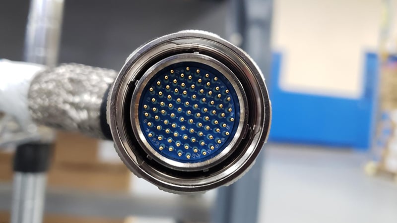
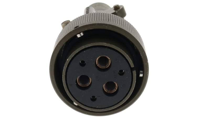
Mil-spec connectors have keyways that require special clocking considerations.
Clocking Orientation
A cable’s clocking orientation determines the relative placement or rotation of connectors, usually using reference features such as keyways, tabs, or markings. The clocking orientation ensures consistent and accurate alignment during the connection process, particularly in systems where large pin counts exist or high-density connections.
To better understand the significance of clocking orientation in custom cable assemblies, let’s explore some commonly used cable types in high-performance applications:
Multi-Conductor Cables
Multiple insulated wires bundled together within a protective sheath. They are designed to transmit various signals, power, and data in complex systems. The number of wires can range from a few dozen to over one hundred, depending on the specific application. UL2464, UL2517, and UL2575.
Shielded Cables
Are typically made of conductive materials like copper braid and foils to protect against electromagnetic interference. Some cables have complex shielding schemes with numerous shielded pairs within an overall braided shield. These shielding layers are crucial in applications where signal degradation or interference must be minimized, such as military communications and aerospace systems. As shielding layers and complexity increase, the cables will stiffen and become difficult to bend.
Armored Cables
Designed with outer metal or fiber braids, or metal tape, to provide enhanced mechanical protection against physical stress, abrasion, and impact. Other cable types are “armored” with flexible conduits or tubing that the center conductors can run within. They are used in environments where cables may be exposed to extreme conditions, including heavy equipment use, combat zones, or aircraft operators.
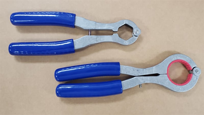
Backshell assembly wrenches are needed to lock connectors in place once clocked to the desired orientation.
Why is Clocking Orientation Important?
The clocking orientation of connectors in a custom cable assembly is critical for several reasons. The first is preventing excessive strain from being placed on the connector and backshell. If the clocking is correctly set on the connector, the assembly should easily mate with its corresponding connector. Incorrect alignment of the connector orientation can lead to electrical faults, equipment damage, or even safety hazards. By ensuring connectors are aligned in the correct clocking orientation, the risk of damage to the keyway or a reversed connection is minimized.
Clocking orientation simplifies the installation and maintenance processes. Jamming the connectors together too hard can damage the keyway and other precision machined alignment features. By aligning connectors in the correct orientation, it becomes easier for technicians to identify and connect cables accurately. This reduces the likelihood of errors, saves time during installation or repairs, and facilitates efficient troubleshooting or system upgrades.
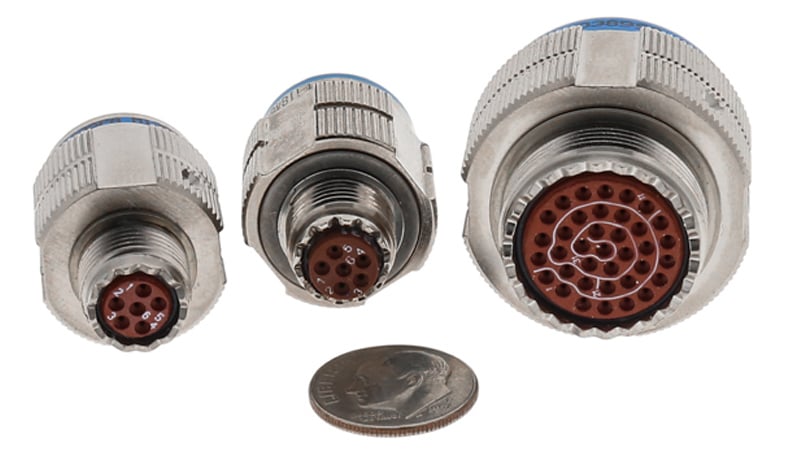
High-density circular connectors are susceptible to damage if not properly routed and strain relieved.
Minimum Bend Radius
The minimum bend radius for an electrical cable refers to the smallest radius at which the cable can be bent without risking damage to its internal conductors, insulation, or shielding. The bend radius is typically specified by the cable manufacturer and depends on factors such as the cable type, size, construction, and material properties. Cables with a very large minimum bend radius can benefit from a properly specified clocking orientation.
Exceeding the minimum bend radius can cause several issues, including:
Stress on Conductors
Bending a cable too tightly can put excessive stress on the conductor’s inside. This stress can lead to conductor breakage, insulation damage, or changes in electrical properties, resulting in signal degradation or even complete cable failure.
Insulation Damage
The insulation surrounding the conductors is designed to provide electrical insulation and protection. Bending the cable beyond its specified bend radius can cause the insulation to stretch, deform, crack, or weaken, compromising its ability to safeguard against electrical leakage or short circuits.
To determine the minimum bend radius for a specific cable, it is crucial to consult the manufacturer's documentation or specifications. These guidelines provide the necessary information to ensure proper cable installation and prevent potential damage. The minimum bend radius is typically expressed as a ratio or a fixed measurement, such as a certain number of times the cable's outer diameter.
It's important to note that different cable types have varying minimum bend radius requirements. For example, shielded multiconductor cables have a larger minimum bend radius compared to similar cables but with a smaller wire AWG. Adhering to the specified bend radius during cable installation and routing helps ensure the cable's longevity, optimal performance, and reliability in its intended application.
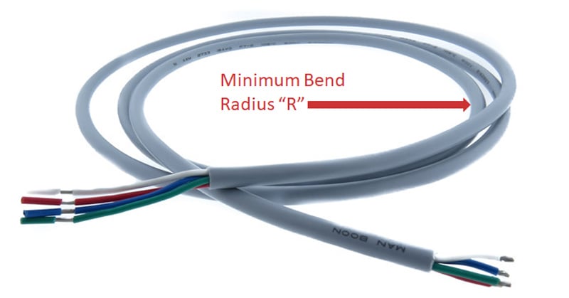
Cables can withstand flexing that does not exceed the minimum bend radius.
Polarized Connectors
The polarized connector ensures that you can't accidentally connect it in the wrong way. Its unique shape or keying mechanism acts like a puzzle piece, fitting perfectly with its counterpart mating connector. This prevents any accident reverse mates, safeguarding against electrical faults and damage to the connectors.
Signal integrity is another crucial aspect. In applications where precise signal transmission is paramount, such as audio or video systems, maintaining the correct signal paths is vital. Thanks to the polarized connector, you can be confident that the connections are aligned correctly, avoiding any signal degradation or loss that could compromise system performance or quality.
Safety is obviously a top concern. Particularly in situations involving high-voltage or high-power connections, the polarized connector plays a key role. By ensuring the connector can only be connected in the right orientation, it minimizes the risk of accidental contact with live or hazardous elements. Still, the connector clocking orientation will need to be specified such that all polarization features align properly.
Keyways
The keyway on an electrical connector refers to a specific feature or slot designed to ensure proper alignment and orientation during connection. The keyway is typically a notch, groove, or protrusion located on the connector body or its mating counterpart. It serves as a physical indicator that aligns with a corresponding feature on the other side of the connection. This ensures that the connector can only be inserted in a specific orientation, preventing incorrect connections that could lead to electrical faults or system malfunctions.
Keyway features help polarized connectors align.
The keyway feature helps simplify the installation process, particularly in applications where multiple connectors are involved or when dealing with connectors in tight or hard-to-reach spaces. It ensures that the connectors are properly aligned and mated, reducing the chances of misconnection or damage to the electrical components.
Additionally, the keyway feature enhances safety by preventing the connection of incompatible or mismatched connectors. It helps avoid situations where different voltages, signal types, or power levels are inadvertently mixed, which could result in electrical hazards or damage to equipment.
Summary
In high-performance applications, custom cable assembly clocking orientation design plays a crucial role in ensuring reliable and efficient communication, power transmission, and data transfer. Engineers utilize advanced design techniques, materials, and manufacturing processes to create cable assemblies that can withstand extreme conditions. Clocking orientation, which determines the alignment and positioning of connectors, ensures accurate signal timing, synchronization, and signal integrity.
By aligning connectors correctly, all polarization features and keyways will mate properly, which then should reduce strain on the cable due to the minimum bend radius and any complex shield designs. When in doubt, build samples first and test to see how the routing and clocking orientation are impacted by subtleties in the cable’s design, then freeze the design with requirements stating that the clocking orientation shall be met within a finite tolerance band.
Key Takeaways
- Clocking orientation ensures proper connector alignment, preventing electrical faults, equipment damage, and safety hazards in high-performance cable assemblies.
- Multi-conductor, shielded, and armored cables require careful clocking, as their stiffness and complexity can make alignment and mating more challenging.
- Minimum bend radius must be considered, as exceeding it can stress conductors, damage insulation, and degrade signal integrity.
- Polarized connectors and keyways enhance reliability, ensuring that cables can only be connected in the correct orientation to prevent reversed connections.
- Clocking orientation simplifies installation and maintenance, reducing errors, saving time, and preventing wear on connectors and backshell assemblies in demanding environments.


