


One of the most common reasons for selecting a custom cable assembly is to satisfy some type of flexibility or bending requirement. Even the bulkiest of electrical cables have some sort of give to them, allowing them to form around corners or be coiled.
Flexible cables are used anywhere motion is expected or where space limitations exist. Typically, the smaller the wire diameter, the more flexible it is. While wire size is one of the most critical variables in determining the overall flexibility of a cable, several other factors influence a cables rigidity.

Wire Size Options
The simplest way to improve a cables’ flexibility is to decrease its outer diameter. Inversely, this means that the higher the wire gauge, or AWG size, the higher the flexibility. All things equal, a 34AWG cable will be much more flexible than a 22AWG cable. While not every application permits a wire size reduction to improve flexibility, this remains the easiest fix to a common problem.
Many common wire classes are available in sequential wire sizes, allowing designers to easily select from several sizes to optimize the flexibility of the cable. Once constructed, cables can be tested to compare the various mechanical and flexibility properties of the final product.
| UL Spec | Wire Size (AWG) | Strand Count | Nominal OD (mm) | Voltage (V) | Max Temp (°C) | Jacket Material | Conductor Material |
|---|---|---|---|---|---|---|---|
| UL 1213 | 34 | 7 | 0.6 | 150 | 105 | Extruded PTFE | SPC / NPC |
| UL 1213 | 32 | 7 | 0.7 | 150 | 105 | Extruded PTFE | SPC / NPC |
| UL 1213 | 30 | 7 | 0.8 | 150 | 105 | Extruded PTFE | SPC / NPC |
| UL 1213 | 28 | 7 | 0.9 | 150 | 105 | Extruded PTFE | SPC / NPC |
| UL 1213 | 26 | 7 | 1 | 150 | 105 | Extruded PTFE | SPC / NPC |
| UL 1213 | 24 | 7 | 1.1 | 150 | 105 | Extruded PTFE | SPC / NPC |
| UL 1213 | 22 | 7 | 1.3 | 150 | 105 | Extruded PTFE | SPC / NPC |
Wire size summary for PTFE jacketed cable.
To those familiar with small gauge electronics wiring, it’s obvious that a 34AWG wire will be much more flexible than a 22AWG one. But how can this flexibility difference be better quantified? Exactly how much more flexible is one cable compared to the other? Since a physical property like cable flexibility is so critical to many design applications, engineers have several ways of safeguarding their design requirements.
What is a Minimum Bend Radius?
One common way to define a cable’s flexibility is to calculate its minimum bend radius. As the name implies, the minimum bend radius of a cable is the tightest corner it can make without incurring some type of damage to the jacket or conductor.
The minimum bend radius is first estimated using preliminary sizing factors to approximate the value. The cable jacket OD (outer diameter) is then multiplied by a factor that is a function to the cable’s cross section, resulting in the estimated minimum bend radius. This factor varies but usually ranges from 6x to 12xand is a function of the application and cable construction. The minimum bend radius factor can also be shifted to account for projects that are expected to have cyclic and extreme motions. Since the cable jacket and conductor can be fatigued prematurely by excessive and frequent bending, the factor may be decreased to compensate for this environment. It is important to note that this calculated minimum bend radius value is a rule of thumb and should be treated as a good-faith estimate. Accordingly, testing must be performed for any design critical applications before full rate production.
| Wire AWG | OD (mm) | Factor | Estimated Minimum Bend Radius (mm) |
|---|---|---|---|
| 34 | 0.6 | 12 | 7.2 |
| 22 | 1.3 | 12 | 15.6 |
For this example, the UL1213 wire minimum bend radius is calculated for both a 34AWG and 22AWG conductor. Both have assumed a worst-case bend factor of 12 to demonstrate the large shift in minimum bend radii. As the wire OD is doubled, so is the expected minimum bend radius. For larger wire bundles like 12AWG through 8AWG, the wire diameter becomes exponentially larger as the size increases, decreasing the overall flexibility of the cable dramatically.
Flexible Conductor Options
If changing the wire size does not solve whatever flexibility requirement exists, there may be other wire construction options available to review. Other variables to consider include modifying the conductor’s cross section or strand count. Stranded conductors are among the most common wire types for electronics applications because of their flexibility and current carrying capabilities.
| Individual Strand Size | Stranded Conductor Diameter | Overall Diameter (OD) | Resistance at Ambient | Nominal Weight |
|---|---|---|---|---|
| AWG | mm | mm | ohm/Km | Kg/Km |
| 25 | 1.5 | 3.06 | 14.6 | 20.09 |
| 29 | 1.5 | 3.06 | 14.6 | 19.7 |
| 33 | 1.5 | 3.06 | 14.6 | 20.08 |
Strand count options for 16AWG wire.
Stranded conductors can be produced in various counts from dozens of individual strands to thousands of strands. For specialty high strand count cables, some of the individual strands are not much larger a human hair. Bunched together in groups of hundreds (or even thousands), these fine wires can create the form of a much larger cable while still exhibiting exceptional flexibility and range of motion. And when grouped together in bundles large enough, these high strand count cables can support current loads comparable to individual 8AWG or 12AWG wires.
How to Get Started
Power management systems and battery applications are constantly pushing the limits of how much power can be crammed inside of small devices. With this requirement comes the need for extremely flexible wires that can be bent and routed through complex assemblies. High-flexibility materials like silicone, PTFE, or softer PVC can be used as a jacket material to better the flexibility benefits of high strand count wire designs. These less common jacket materials such as PTFE or silicone come with additional benefits such as temperature range increases, enhanced fatigue life, or a resilience to chemicals and UV.
Some cables cross sections may be appropriate for further customization opting for non-uniform shapes like extruded flat cables and rectangular cross sections. These changes can yet again improve a cable’s flexibility in a specific bending configuration, furthering its ability to be bent and routed through narrow openings.
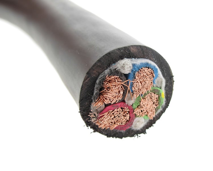
High strand count wire cross-section.
Summary
It is clear that flexible wires warrant customization of both the wire jacket and copper conductors to be truly effective. At the same time, it can be risky, expensive, and counterproductive to immediately jump into production with an expected cable solution that could take weeks and thousands of dollars to fabricate with little guarantee it will work. A qualified cable manufacturer can help offer guidance on options, timelines, and risks early in the process allowing for a faster time to market. Initially all that is required to begin the discussion is a rough outline of the cable length, its approximate wire size, and what type of connectors are required. From there, a full-service manufacturer like Epec can help walk through the various design complexities that need to be addressed on the way to production.
Key Takeaways
- Wire size directly impacts flexibility, with smaller gauge (higher AWG) wires offering greater flexibility, making them ideal for applications requiring tight bends and frequent motion.
- Minimum bend radius is a critical design factor, ensuring cables can be bent without damaging conductors, insulation, or shielding, which is essential for reliability in high-flex applications.
- Stranded conductors improve flexibility, with higher strand counts allowing cables to bend more easily while maintaining current-carrying capacity, making them ideal for power and signal applications.
- Jacket material selection enhances performance, with high-flexibility materials like PTFE, silicone, or soft PVC providing increased durability, temperature resistance, and improved fatigue life.
- Custom cable designs optimize flexibility and routing, with options such as extruded flat cables, rectangular cross-sections, and non-uniform shapes improving bend characteristics in space-constrained applications.


