


Identifying the differences between rigid PCB FR4 materials and flex circuit polyimide materials can be useful to customers who are implementing flex circuit designs for the first time. Beyond the obvious difference in flexibility, the two types of materials have different available thicknesses, copper types, and properties that impact high-speed controlled impedance signals.
In this blog post, we will review the above as a primer for developing a flex design from a rigid PCB knowledge base.
Flex Circuit Material Construction Differences
FR4 is comprised of three materials: Epoxy Resin, one or more layers of woven fiberglass mat, and copper. The number of glass matt layers will depend upon the thickness of the FR4. The fiberglass layers are impregnated with the epoxy resin and then the resin with the added external copper layers is laminated to a fully cured state under heat and pressure.

Polyimide flex circuit materials are comprised of two materials: single-stage high-performance polymer plastic and copper. The flex material is manufactured by casting liquid polyimide onto a copper layer and then curing the material to its solid state which as plastic is very ductile. For both materials, there are additives that allow the materials to meet UL94V-0 flammability requirements and colorize if necessary. FR4 resins can also have different formulations that improve the temperature rating and the dielectric constant for higher performance applications. Lastly, there is also a hybrid rigid material that uses a polyimide-based resin combined with fiberglass matt layers for very high temp. applications.
The key difference is the brittleness of the cured epoxy and the woven fiberglass matt in rigid materials that provide a high degree of stiffness. Polyimide flex materials are non-reinforced which allows for the full ductility of the plastic polyimide resin. Thin rigid materials can be bent but have a very limited bend capability. If the epoxy or glass matts start to fracture, when bent, the integrity of the part is compromised and can easily cause cracked circuits.
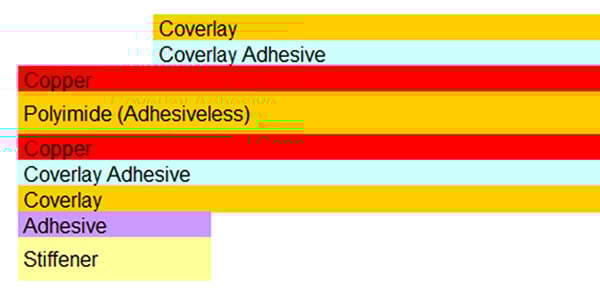
Polyimide flex circuit material cross-section.
Material Property Differences
Three key material property differences between standard FR4 materials and polyimide flex materials are the dielectric constant (DK), the maximum continuous operating temperature and moisture absorption.
The temp rating and DK values for both are derived from the resin system used. FR4’s epoxy-based resin limits the maximum operating temp to the 150°C range while polyimide is 300°C. The hybrid Polyimide based rigid material has a higher temp rating, approx. 220°C, due to the Polyimide based resin. Polyimide Flex materials also have a better dielectric constant (DK) value in the 3.2 – 3.4 range. Standard FR4 has a 4.0 – 4.4 DK. The actual value is dependent upon the signal frequency.
Polyimide materials, as a natural property, absorb moisture up to 2 % by weight while FR4 is 0.1% or less. The added moisture absorption for polyimide does not change or negatively impact its mechanical or electrical properties. It does however need to be baked dry prior to assembly to prevent the entrapped moisture from flashing to steam and potentially causing delamination of the layers, coverlays, or stiffeners.
In addition to the above, there are additional material property differences of which the majority do not impact a design.
Material Thicknesses & Copper Types
Polyimide flex materials are thinner than that of FR4 materials. This is due to the lack of reinforcement and the ductility of the cured resin. FR4’s epoxy-based resin cures to a hard and somewhat brittle state while polyimide remains very ductile. The minimum FR4 thickness is also restricted by the glass weave. The standard thickness range for flex materials is ½ to 3 mils while FR4 can range from 2 to 125 mils. Copper thicknesses are similar with a standard range of 1/3 OZ to 2 OZ. Thicker and thinner copper is also available for both materials if needed.
The main difference is the type of copper available in polyimide flex materials. FR4 materials use electrodeposited (ED) copper which has a vertical grain structure. This type of copper is available in flex materials however the more common type is rolled annealed (RA) copper. Standard ED copper is converted through a rolled annealed process to create a horizontal and elongated copper grain structure. This allows for a higher degree of ductility which is critical to ensuring mechanical reliability in tight static bend and dynamic bend applications. Dynamic applications must use RA copper. Due to the elongated grain structure, RA copper has a grain direction that needs to be oriented in the length of the flexed area to derive the maximum benefit.
Impact on Impedance Controlled Circuits
Polyimide flex materials have two inherent advantages over FR4 materials when used in a design with controlled impedance. The lower DK allows for thinner cores which when combined with thinner line widths and spacings reduce the thickness of a flex design and allow for a tighter minimum bend radius. Flex materials are also completely uniform and do not have the small discontinuities caused by the woven glass matt in rigid materials. High-end rigid materials have minimized this, by altering the configuration of the glass matt, but at added cost.
Summary
While not a true apples-to-apples comparison, it is still valid to understand the differences in these two materials when in the early stages of implementing a flexible circuit board design. There have also been designs that have utilized flex materials within a rigid-only PCB design to take advantage of the properties of polyimide. Please feel free to contact Epec if you have any questions or need more information.
Key Takeaways
- Flexibility Comes from Material Composition: FR4 contains rigid fiberglass and epoxy resin, making it stiff and prone to cracking when bent. Polyimide is non-reinforced and highly ductile, which allows it to flex and bend without damage, making it ideal for dynamic or tight bend applications.
- Temperature and Electrical Properties Differ: Polyimide has a much higher continuous operating temperature (up to 300°C) and a lower dielectric constant (3.2–3.4) compared to FR4 (150°C and DK of 4.0–4.4), making it better suited for high-temperature and high-speed signal applications.
- Moisture Absorption Needs to Be Managed: While polyimide absorbs more moisture than FR4 (up to 2% by weight), it doesn’t degrade its performance. However, it must be baked before assembly to avoid delamination caused by moisture turning to steam during reflow or soldering processes.
- Copper Type Matters for Flex Durability: Flex circuits commonly use rolled annealed (RA) copper instead of the standard electrodeposited (ED) copper used in FR4. RA copper’s horizontal grain structure improves ductility and is essential for applications with repeated or tight bending.
- Flex Offers Impedance Control Advantages: The uniform structure and lower dielectric constant of polyimide materials allow for more consistent controlled impedance and thinner constructions. These benefits help reduce the bend radius and improve high-speed signal integrity compared to FR4.


