


When developing a flex PCB based design, one of the most common early decisions is whether a flex circuit with stiffener(s) will meet the design requirements or if a rigid-flex construction is necessary or more effective. While there is some overlap between the two methodologies, there are significant capability, performance, and cost differences that require review to ensure a successful design.
IPC Definitions
A flexible circuit board with stiffener design is classified by IPC as a type 1, 2, or 3, depending upon the layer count, and is defined as a one or more circuit layer flex circuit with stiffener. The stiffener is not part of the electrical interconnect of the design, with a few minor exceptions defined later in this article, and performs a mechanical function only.
Rigid-flex circuit board designs are classified as IPC type 4 and defined as a multilayer rigid and flexible material combination containing two or more layers with plated component and or via holes. The integration of flex layers within a rigid PCB construction allows multiple rigid areas to be interconnected together without any additional connectors or wiring.

Functionality: Flex PCB with Stiffeners
Flexible circuits manufactured with stiffeners serve the following functions in a flex PCB design:
- Mechanical support to specific areas of the design that contain SMT and/or PTH components. Prevents the flex circuit from being bent at or near components which if allowed could compromise the integrity of the solder joints.
- Localized increase in thickness required to meet ZIF connector specifications
- Heat dissipation
Stiffeners do not have plated holes and have no electrical interconnect to the circuitry in the flex layers.
For flexible circuit board designs that have stiffeners on both sides, but in different areas due to component placement requirements, this will add significant complexity and cost at assembly. Stiffeners on the same side as SMT components will prevent solder past stencils from lying flat in the SMT areas and may necessitate a rigid-flex construction.
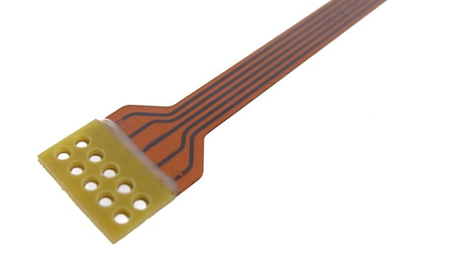
Flexible circuit board designed with stiffeners
Functionality: Rigid-Flex PCB
Rigid-flex PCBs provide the same functionality and capability of rigid PCB technology.
- Added benefit of fully integrated connections between rigid areas. Eliminates the need for added connectors, which reduces the real estate requirements, and all the additional points of interconnect required by the connectors. This, in turn, improves the reliability of the design by eliminating potential points of failure
- Allows for SMT components on both sides in the same area(s)
- Blind and buried via capable
- Full depth PTH holes for higher reliability PTH component interconnect.
- Allows for Press fit connectors
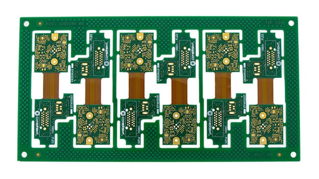 Rigid-flex circuit board designed without stiffeners
Cost Impact
A flexible circuit with stiffener design will, with few exceptions, be more cost effective than that of a comparable rigid-flex at the individual part level. This is due to the added materials and manufacturing process steps required by rigid-flex technology. This cost difference can range easily from 2x or greater.
This, however, does not define that a rigid-flex solution will be overall more expensive than that of a flex with stiffeners once all additional cost factors are accounted for. The added benefits of higher-level integration, reduced component requirements, improved highspeed signal performance, and reduced higher level assembly requirements can result in a rigid-flex based solution being more cost effective.
Materials: Flex PCB with Stiffeners
Stiffeners are most commonly manufactured from either FR4 or polyimide.
FR4 is cost effective and typically used to support component areas, due to its higher rigidity than polyimide. Thicknesses vary from 0.008” to 0.059” or greater.
Polyimide is used for increasing the thickness at, and providing support for, ZIF connector contact fingers. It allows for the tight tolerance of the flex thickness and part outline at the contacts as called out by the connector specifications. Typically, at the finger area, flex thickness tolerance is +/- 0.002” and outline width is +/- 0.003”. Polyimide is also used to limit bend capabilities in specific areas to facilitate installation in the final assembly, reinforce mounting hole locations and provide added wear resistance if there is an abrasion concern.
Stiffeners can also be manufactured from aluminum or stainless steel as well as other materials. Aluminum is commonly used for designs that require heat dissipation. Stainless steel is used when the design has space limitations on the stiffener thickness and a higher level of support is required than what an FR4 stiffener of the same thickness can provide. Both materials are added cost factors, can extend delivery times, and may have minimum order quantity requirements.
Materials: Rigid-Flex PCB
Rigid-flex circuit boards utilize the same materials as rigid PCBs and flex circuits but differ in the type of pre-preg used. The pre-preg required has a reduced flow capability and is referred to as either “no-flow” or “low- flow”. It is the same material as standard full flow pre-preg but is cured to a higher level prior to use in lamination. This increased cure state prevents the pre-preg from being extruded out between layers and onto the surface of the interconnecting flex sections. If allowed to occur, this would violate IPC-6013 specifications and result in a finished part that is non-functional or that is easily broken when bent. The necessary low-flow format of the pre-preg is not available in all types of rigid materials. It’s reduced flow characteristics also require a thicker amount to ensure a proper lamination.
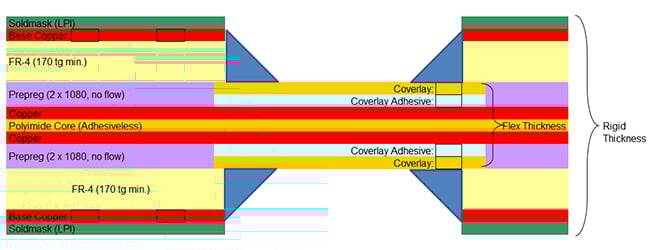
Example of a standard 4-layer rigid-flex PCB construction
Design: Flex with Stiffeners
Stiffeners can be incorporated in flex design to meet a wide variety of requirements:
- Can be applied to one or both sides of the design
- Can vary in thickness and material within the same design
- Attached with either thermo setting flex adhesive or pressure sensitive adhesive (PSA), ZIF connector applications require thermo set adhesive.
- Silkscreen and PSA allowed on external layer of stiffeners
- Electrical shielding layers, if required, cannot extend under stiffeners due to slip priorities of the external layer of the shielding film materials
- Advanced FR4 stiffeners can have circuit layers but without electrical interconnect to the flex layers.
Common applications are:
- Component mounting pads to allow for soldering of connector mounting lugs from both sides for added strength
- SMT pads for edge mounted connectors
- Additional localized circuit requirements
Example of 3-layer flex circuit with fr4 and polyimide stiffeners both sides
Design: Rigid-Flex PCB
The primary advantage is the integration of both rigid PCB and flex technology which allows for designs that can achieve significantly tighter packaging requirements than any other solution. Also provides for higher level performance and reliability by eliminating the points of interconnect required by connectors and wiring.
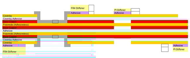
Stiffeners are also commonly utilized in rigid-flex designs, in the flex areas, serving the same purposes as in flex only designs. Designs can incorporate flex sections, or tails, that terminate in ZIF contacts and, as such, require a polyimide stiffener to meet the ZIF connector specifications. Flex areas may also have components which then require FR4 stiffeners for support and reliability.
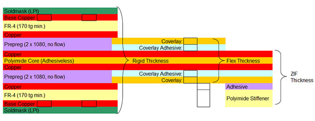
Example of a 6-layer rigid-flex PCB with 2-layer ZIF flex tail.
Summary
The capabilities of flex with stiffeners and rigid-flex allow for an extremely wide variety of combinations and solutions. When combined with the overlap in capabilities, this can complicate the decision-making process early in the design. Rigid-flex designs can always meet the capabilities of flex with stiffeners though often but not always come with an unnecessary cost premium. Flex with stiffeners, while generally more cost effective, may incur additional costs elsewhere in the finished assembly.
Our recommendation to all our customers is to engage with our engineering at the early stages. Once we understand the design parameters, we can assist in narrowing down the options to a few configurations that merit further investigation and provide as accurate as possible preliminary costing to factor in to the decision-making process.
Key Takeaways
- Flex with Stiffeners vs. Rigid-Flex: Flex PCBs with stiffeners (IPC Type 1–3) use added mechanical layers for support but have no electrical interconnect, while rigid-flex PCBs (IPC Type 4) integrate rigid and flex layers for full electrical and mechanical functionality.
- Functionality & Use Cases: Stiffeners provide localized support for components, meet ZIF connector thickness requirements, and help with heat dissipation. Rigid-flex PCBs enable integrated connections between rigid areas, eliminate the need for additional connectors, and support advanced features like blind/buried vias and press-fit connectors.
- Cost Considerations: Flex with stiffeners is typically less expensive per part than rigid-flex, sometimes by 2x or more. However, rigid-flex can reduce overall system costs by eliminating connectors, improving reliability, and minimizing assembly steps.
- Material Differences: Stiffeners are commonly made from FR4 or polyimide, with aluminum or stainless steel used for heat dissipation or added support. Rigid-flex PCBs require specialized “no-flow” or “low-flow” pre-preg to prevent resin from seeping into flex areas during lamination.
- Design Flexibility: Both approaches support complex designs. Stiffeners can vary in material, thickness, and placement, while rigid-flex allows tighter packaging, higher reliability, and integration of components on both rigid and flex sections.


