


Integrating flex circuits with rigid PCBs in a rigid-flex configuration helps address common design challenges by combining the mechanical advantages of flex circuitry with the functionality of rigid circuit board sections.
This approach can improve reliability, reduce packaging requirements, support controlled impedance performance, and lower assembly complexity. Although rigid-flex PCB designs may increase unit cost, many applications realize overall benefits through improved performance and assembly savings.
Flex Circuit Technology
Rigid-flex technology combines flex circuit layers and rigid PCB sections into a single integrated structure. By leveraging the flexibility of flex circuits and the functionality of rigid circuit boards, designers can achieve improved mechanical and electrical performance while reducing design and assembly constraints.
Key advantages include:
- Improved reliability through the elimination of interconnect points
- Reduced packaging and space requirements
- Better controlled impedance performance and signal integrity
- Lower assembly complexity and fewer assembly errors
- Potential reductions in overall assembled system cost
While rigid-flex designs may carry a higher unit cost than other interconnect approaches, the resulting reliability, packaging, and assembly benefits can provide significant overall value.

Reliability Improvement Through Elimination of Interconnect Points
One of the primary benefits of rigid-flex design is the reduction or elimination of interconnecting points between rigid circuit board sections. Fewer interconnects mean fewer potential failure locations within the system.
 Example of Rigid to Flex Via Interconnects
In a rigid-flex design, flex circuit layers are incorporated directly into the rigid sections. Connections between rigid and flex regions are created through plated via holes that pass through both rigid and flex layers. As a result, the rigid-flex assembly functions as a single integrated unit without the separate connection interfaces required by alternative approaches.
For high-reliability applications, this reduction in interconnect points is often a compelling reason to implement rigid-flex technology.
Comparison of Typical Interconnect Approaches
The following examples compare a design containing 20 circuits connecting two rigid PCB sections.
Wired Solution
Requirements:
- Two sets of male/female connector pairs
- Ribbon cable
Interconnects can total 120 where sources include:
- PCB-to-connector solder joints
- Male-to-female connector connections
- Connector-to-wire contacts
 Wired Solution for Rigid PCB
Flex Ribbon Circuit with ZIF Connectors
Requirements:
- Two ZIF connectors
- Flex circuit cable
Interconnects can total to 80 where sources include:
- PCB-to-ZIF connector solder joints
- ZIF connector-to-flex circuit contacts

Flex Ribbon Circuit and ZIF Connectors
Board-to-Board Stacking Connectors
Requirements:
- One set of male/female connectors
- PCB-to-male connector solder joints
- Connector contacts
- PCB-to-female connector solder joints
Interconnect sources total 60 where sources include:
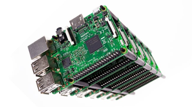
Board-to-Board Stacking Connectors
Rigid-Flex PCB Design
Because rigid-flex eliminates these interface connections down to 0, it reduces potential failure points while simplifying the overall interconnect structure.
Enhanced Mechanical Reliability
Mechanical reliability can also improve when compared with wired solutions.
Benefits include:
- Reliable flexing characteristics
- Reduced overall system weight
- Improved suitability for applications with shock and vibration requirements
- Elimination of mechanical weaknesses associated with multiple interconnect interfaces
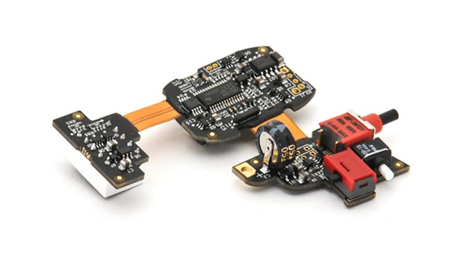
Rigid-Flex PCB with no Points of Interconnect
Packaging Improvement Through Elimination of Connector Footprints
Rigid-flex technology can reduce the physical size of the rigid circuit board sections by eliminating connector footprints within the layout.
Space previously dedicated to connectors can instead be used to:
- Reduce rigid circuit board dimensions
- Simplify design complexity
- Add functionality within the same footprint
Additional layout benefits may also be realized because circuitry does not need to be routed to external-layer connectors. This can reduce:
- Via requirements
- External trace routing
- Layout congestion
- Overall Gerber layout space requirements
Reducing Overall Package Size
Beyond reducing connector footprint requirements, rigid-flex PCB designs can significantly reduce total package size.
The thin construction and bendability of flex circuits allow rigid sections to be positioned closer together than is typically possible with wired interconnect solutions. This capability is particularly valuable in applications where available space is limited.
As a general rule, rigid-flex consumes 10% of the space and weight of a wired solution.
Flex circuits achieve these reductions through:
- Thinner material constructions
- Smaller line widths and spacings
- Tighter bend radiuses than wired alternatives
Because flex materials occupy less space and support tighter bends, rigid sections can be packaged more efficiently while maintaining electrical connectivity.
Performance Improvement Through Controlled Impedance
Rigid-flex designs can provide important advantages for applications requiring controlled impedance and high-speed signal performance.
By eliminating connector interfaces and associated connection points, rigid-flex PCB designs reduce discontinuities within signal paths. Fewer discontinuities can contribute to improved signal integrity between rigid sections.
Flexible PCB materials also provide characteristics that support impedance control:
- Lower DK values than many rigid materials
- Uniform material thickness
- Consistent impedance performance
- Support for stripline configurations
- Support for surface microstrip configurations
The thin construction of controlled impedance flex circuits also enables tighter bend radii and more compact packaging than comparable wired interconnect approaches.
What Does Impedance Mean in This Context?
In this application, impedance refers to the electrical characteristics of high-speed signal paths. Rigid-flex circuit board designs can help maintain consistent impedance values by reducing signal discontinuities associated with connectors and by utilizing flexible PCB materials with uniform thickness and favorable electrical properties.
Reducing Assembly Cost and Complexity
Rigid-flex PCB technology can also simplify manufacturing and assembly.
Because rigid sections are integrated into a single structure:
- Additional assembly operations between rigid sections are not required
- Connector components can be eliminated
- Connector assembly costs can be eliminated
- Manual assembly steps can be reduced
- Assembly errors are minimized because components fit together in only one configuration
For designs that would otherwise use wires or flex circuits soldered directly to rigid PCBs, rigid-flex can reduce both labor requirements and opportunities for assembly-related errors.

Summary
Integrating flex and rigid PCB technology brings capabilities beyond those of many other solutions, which solves challenging design requirements. These capabilities can significantly improve a project by enhancing the reliability, reducing the packaging/size requirements, improving the electrical performance, and potentially reducing the total assembled cost of a finished design.
Key Takeaways
- Improved reliability: Rigid-flex eliminates interconnect points between rigid boards, reducing potential failure points and enhancing performance in high-reliability applications.
- Packaging efficiency: Connector footprints are eliminated, freeing up valuable PCB real estate for smaller designs, simpler layouts, or added functionality.
- Smaller overall size and weight: Flex consumes about 10% of the space and weight of wired solutions, with thinner materials enabling tighter bend radii and closer packaging of rigid sections.
- High-speed performance: Consistent impedance values, reduced signal discontinuities, and better material properties improve signal integrity in designs with controlled impedance.
- Lower assembly cost and complexity: By removing connectors and manual soldering between rigid sections, rigid-flex designs cut assembly steps, costs, and errors.


