


Keypads that utilize dome switches, silicone elastomer keys, or tactile switches rely on actuation force as a critical feature to define how much load is required to close the normally open switch. In this context, force is a vector acting normally to the keypad surface and is usually defined in grams (g) or pound force (lbf).
Early in some projects our customers aren’t critical of the exact force required to trip the switch, and will rely on a low, medium, or high force rating to mature a design. While this low, medium, and high force rating system is less than ideal since it’s reliant on human perception, it does allow for an order of magnitude force design to be targeted for any new design. To add quantifiable definition to an otherwise arbitrary scale, Epec's engineering team recommends the following guidelines:
Force Definitions:
- Low Force: 50g - 200g
- Medium Force: 200g - 450g
- Hard Force: 450g+
Force Tolerances:
- General rule of thumb is +/- 10%
- Some tactile switches have a +/- 50% tolerance
How Material Stack-Up Impacts Perceived Force
Have you ever picked up a membrane switch attempting to operate it before it’s affixed to a panel? Or, have you tried to actuate one of the buttons while holding the membrane switch your hand? If so, you may have noticed it was difficult to discern the click of the dome switch or detect when the button was depressed. Maybe the engineer next to you offered some advice, telling you to place it on a flat surface and try again.
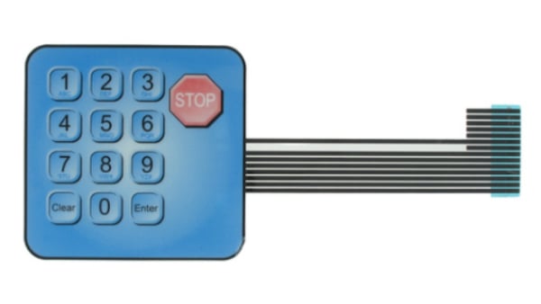 Example of a Membrane Switch Before Being Affixed to a Panel
If any of these scenarios sound familiar, you have just become acquainted with Hooke’s Law - the relationship between force, displacement, and elastic bodies.
This is important because membrane switches act as a system to create a perceived force to the user. This perceived force is the accumulation of multiple materials and devices that act in concert to provide the user with a sensed force necessary to actuate the switch. For example, if two identical membrane switches are panel mounted, and say device A is mounted to a 1” rigid steel panel, and device B is mounted to a 1/8” aluminum panel that has some flex, which device will require more force to operate? The answer is device B, because the 1/8” aluminum panel is more flexible compared to the steel panel, by deflecting more under an equal load it will be more difficult to trip the switch on device B even though the membrane switch is the same. This is because when subjected to the same point force, the panel on device B reacts with a greater deflection when compared to device A, and the panel is essentially absorbing some of the force/motion just as a spring does in Hooke’s law.

Breaking Down the System
The typical membrane switch assembly consists of laminated layers of polyester, adhesive, electrical circuits, and discreet components like LEDs and domes. Including the panel which the membrane switch adheres to (either through screws or adhesive), all these layers have their own physical properties and stiffnesses (kx). According to Hooke’s law, the stiffness coefficient kx is the relationship between force applied and distance traveled. The diagram below describes how each individual layer has its own stiffness and when summed up, creates the perceived system stiffness. The total effective stiffness of your system, kmembrane switch, is the addition of all the individual layers and components. The individual layers stiffness values are typically a function of the material properties themselves but can also be impacted by the buttons’ geometry. For example, narrowing the width of a membrane switch may increase the force required to trip the switch, making it harder to register a switch closure event.
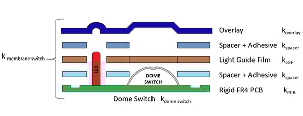 Diagram of Membrane Switch Construction
Why This Is Important
This is important for several reasons. First, if your engineer specifies a dome switch with a specific actuation force rating, you may notice that once assembled in a membrane switch you will require much more force to trip this switch. A 320g force stainless steel dome switch typically has a +/- 30g tolerance assumed when tested alone on a flat rigid surface.
In theory, this would mean that the maximum force required to actuate this switch would be 350g. However, once assembled inside a membrane switch, you may observe that it takes in excess of 900g of force to trip the dome switch. This is due to the explanation above that the entire system works together to yield a perceived stiffness to the user. This example holds true with PCB mounted tactile switches and other discrete components that are intended to be integrated within laminated keypads.
Another reason this is important is that footprint changes to your membrane switch or button can impact the perceived tactile force required to trip the switch. Like the oil canning effect of a sheet metal panel, a normal force applied to the surface deflects the material a certain amount. Changes to the surface area or footprint dimensions can impact the amount of force required to deflect the material and also change the amount of deflection observed. So, if a redesign reduces the width of your membrane panel from 2 inches to ¾”, and the PCB mounted tactile switches are kept constant, don’t be surprised if the tactile response between the two systems is not equal.
How to Plan for Differences in Tactile Response
Unfortunately, it is difficult to measure the exact actuation force empirically, and even more difficult to estimate through calculation. For this reason, Epec Engineered Technologies employs the use of production samples for all new designs. This allows our customers to evaluate physical specimens and make changes before full-rate production is launched, tooling is complete, and the design is frozen. A property as important as tactile response or actuation force is critical for key stakeholders to review.
There are special circumstances where our customers request multiple samples with different force ratings for evaluation. Stakeholders can select which variant they prefer and solicit internal approval before production starts. It should be noted that this can delay your product launch, however may be necessary to get the design right.
Summary
Actuation force is one of the most important characteristics in keypad design, yet it is often misunderstood because the perceived force depends on more than just the switch itself. The full system, including dome switches, adhesives, circuit layers, and the mounting panel, works together to create the tactile response users feel. Panel stiffness, material properties, and design geometry can all increase or decrease the required actuation force, sometimes far beyond the switch’s rated specification.
Because these variables are difficult to predict through calculation alone, building and testing production samples is the most reliable way to evaluate tactile performance. This approach allows engineers and stakeholders to compare options, refine designs, and ensure the final keypad meets both functional and user experience requirements.
Key Takeaways
- Actuation force defines how much load is needed to close a switch, typically measured in grams or pound force, and can be categorized as low (50–200g), medium (200–450g), or hard (450g+).
- Perceived force is influenced by the entire material stack-up, including panels, adhesives, domes, and circuits, not just the switch itself.
- Panel stiffness plays a major role, with more flexible mounting surfaces absorbing force and making switches feel harder to actuate.
- Design geometry impacts tactile response, as narrowing a panel or button footprint can increase the force required for actuation.
- Production samples are essential for validation, since true tactile response is best evaluated with physical builds before finalizing tooling and production.


