


Stiffeners are a critical element in flex circuit design and directly influence the performance, reliability, and manufacturability of the finished product. Properly specified stiffeners provide support for component and connector areas, help meet ZIF connector requirements, address mechanical bend constraints, and can assist with heat dissipation. Complete and accurate documentation is essential to ensure the finished flex circuit meets design requirements.
Understanding the Role of Stiffeners in Flex Circuit Design
Most flex circuit designs rely on stiffeners to provide localized mechanical reinforcement without sacrificing the flexibility of the overall circuit. Because stiffeners affect both the physical performance and manufacturability of the design, they must be fully defined within the fabrication data set.
 Flex Circuit with Connector Area Support Stiffeners
Incomplete or inaccurate stiffener documentation can result in flex circuits that do not meet required form, fit, or functional requirements.
Common purposes of stiffeners include:
- Component and connector area support
- Thickness modification to meet ZIF connector specifications
- Mechanical bend constraint management
- Heat dissipation support
Each application has distinct material selection and design requirements.

Choosing the Appropriate Stiffener Material
The most commonly used stiffener materials are FR4 and polyimide, although aluminum and stainless steel are used in specialized applications.
FR4 Stiffeners
FR4 stiffeners are primarily used to reinforce areas that contain components or connectors.
 Flex Circuit with FR4 Stiffener
By supporting these regions, FR4 stiffeners help prevent flexing near soldered components and connectors where bending could compromise or crack solder joints. This localized reinforcement improves mechanical stability while protecting critical electrical connections.
Typical FR4 Thicknesses
- FR4 stiffener thickness range = 0.010–0.059 inches
- Common thickness = 0.020 inches
- Common thickness = 0.031 inches
- Common thickness = 0.039 inches
FR4 is typically selected when maximum support in component and connector areas is required.
Polyimide Stiffeners
Polyimide stiffeners are most commonly used in flex circuits that interface with Zero Insertion Force (ZIF) connectors.
ZIF connector specifications require a precise thickness at the exposed contact finger area to ensure reliable engagement with the connector. Rather than increasing the thickness of the entire flex circuit, a polyimide stiffener can be applied locally to achieve the required thickness only where needed.

Flex Circuit with Polyimide Stiffener
This approach helps preserve the flexibility and bend performance of the circuit while avoiding the cost and mechanical limitations associated with increasing the thickness of the entire design.
Common ZIF Thickness Requirements
- Common ZIF finger thickness = 0.3 mm
- Common ZIF finger thickness = 0.2 mm
ZIF connector requirements often include:
- Specific finished thickness at the contact finger area
- Tight profile width tolerances
- Precise finger positional accuracy
- Minimum stiffener length requirements
Polyimide is uniquely suited for these applications because it allows the part outline and stiffener profile to meet the connector's dimensional requirements.
Polyimide for Thin Component Areas
Polyimide may also be used in component or connector locations where total thickness restrictions prevent the use of FR4.
When the design requires a thickness below the practical FR4 limit of 0.010", polyimide can provide reinforcement while maintaining a thinner overall construction. Although it does not provide the same level of support as FR4, a polyimide stiffener may still be preferable to having no stiffener at all.
Aluminum and Stainless-Steel Stiffeners
Aluminum and stainless steel are used less frequently and generally carry a significant cost premium compared with FR4 and polyimide.
Aluminum
Aluminum is commonly selected for designs that require heat dissipation.
Stainless Steel
Stainless steel is typically used when space for stiffeners is limited, but additional component area support is needed beyond what an equivalent thickness FR4 stiffener can provide.
Stiffener Attachment Methods
Stiffeners can be attached using either a thermal bonding adhesive or a pressure-sensitive adhesive (PSA).
Thermal Bonding Adhesive
Thermal bonding adhesive is generally the preferred attachment method.
Benefits include:
- Permanent bond
- Laminated under heat and pressure
- Uses the same flexible epoxy or acrylic adhesive systems commonly used for coverlay attachment
- Typically more cost-effective than PSA attachment methods
Pressure-Sensitive Adhesive (PSA)
Certain design requirements may necessitate the use of PSA attachment.
PSA attachment characteristics include:
- Double-sided tape applied by hand
- Used when design limitations prevent thermal bonding
- Required in some specialized applications
For heat dissipation applications, thermally conductive PSAs must be used.
It is important to note that thermally conductive PSAs are not rated to withstand assembly reflow temperatures. As a result, stiffeners using these materials must be attached after component assembly.
Video: How Automated Stiffener Placement Enhances Flex Circuit Reliability
Additional Design Requirements for ZIF Applications
ZIF connector areas have specific mechanical requirements that must be incorporated into the stiffener design.
 Recommended Flex PCB Dimensions

Recommended ZIF Connector Stackup
To ensure proper connector engagement, the stiffener must produce:
- The required finished thickness across the contact finger region
- Tight profile width tolerances
- Accurate finger positioning
- The minimum specified stiffener length
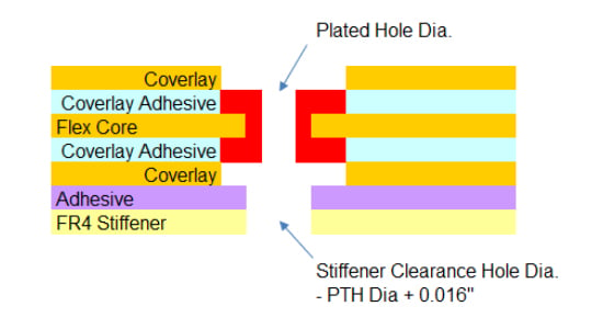 FR4 Stiffeners with Plated Through Hole Design
Because connector engagement depends on these dimensional requirements, accurate documentation is essential.
FR4 Stiffener Requirements for PTH Designs
Designs incorporating plated through-hole (PTH) components and connectors have additional FR4 stiffener requirements beyond those found in SMT-only designs.
Stiffener Placement
The stiffener must be located on the same side of the circuit from which the PTH components are inserted. This provides access to component leads and solder pads during assembly.
 Stiffener Callout in Material Stack-Up
Clearance Hole Requirements
Clearance holes are required to allow component pins to pass through the stiffener.
Oversize Clearance Requirement
- Clearance hole oversize = 0.016 inches
- Hole location tolerance = ±0.005 inches
Oversizing the clearance holes helps prevent overlap between the stiffener openings and plated holes in the flex circuit due to manufacturing and material tolerance accumulation.
Non-Plated Tooling Holes
Clearance holes for non-plated tooling holes are also typically oversized by 0.016" relative to the required hole size in the flex circuit.
If the design requires identical hole sizes in both the circuit and the stiffener, a secondary drilling operation is required.
Secondary Drilling Tolerance
This requirement exists because of manufacturing tolerance considerations.

Documentation Requirements for Accurate Data Sets
To fully define stiffener requirements, the fabrication data package should include complete documentation for all stiffener features.
Stiffener Dimensions and Outlines
Provide:
- Additional mechanical Gerber files (preferred)
- Or 1:1 DXF files
- One file for each stiffener type, thickness, and side
Examples include separate files for:
- 100 µm stiffeners on the top side
- 100 µm stiffeners on the bottom side
- 200 µm stiffeners on the top side
Stiffener dimensions may also be defined within the mechanical drawing.
Material Type
The material type should be identified through:
- Drawing notes
- Material stack-up documentation
Stiffener Callouts
Callouts should be defined in:
- Drawing notes
- Material stack-up documentation
Attachment Method
Attachment methods should be specified in the material stack-up documentation.
Attachment Side
Attachment side requirements should be clearly identified within the design documentation.
Drill Files and Hole Sizes
For PTH designs, provide:
- Additional drill files
- Associated drill charts
ZIF Connector Information
Include:
- ZIF connector manufacturer information
- ZIF connector part numbers
- Location references when multiple ZIF connectors are used
This information should be documented within the mechanical drawing and drawing notes.
Manufacturability Considerations
Stiffeners are fundamental to achieving the required form, fit, and function of a flex circuit. Because stiffener design can affect fabrication and assembly processes, complex requirements should be evaluated early in the design cycle.
Some stiffener configurations may introduce manufacturing challenges or increase assembly complexity. Collaborating with engineering resources early can help identify potential issues and ensure the design remains manufacturable while meeting performance requirements.
Summary
Stiffeners are an important element in most flex designs and as such need to be engineered into the design and fully documented in the data set to ensure the form, fit, and function of the finished flex circuit parts.
Some designs may have complex stiffener requirements that may impact the manufacturability of the flex circuits and may create added complexity in the component assembly process. For these designs we recommend that our customers consult with our engineering team to ensure the flex circuit is both manufacturable and will meet your requirements.
Key Takeaways
- Stiffeners provide support for component areas, ZIF connector interfaces, bend constraints, and heat dissipation requirements.
- FR4 is commonly used for component and connector support and is available in thicknesses from 0.010" to 0.059".
- Polyimide is commonly used to meet ZIF connector thickness requirements while preserving flex circuit bend performance.
- Aluminum and stainless-steel support specialized requirements including heat dissipation and high-strength reinforcement.
- Thermal bonding adhesive is generally the preferred attachment method due to its permanent bond and cost advantages.


