Companies rely on engineering departments to design and develop parts and assemblies for machinery and applications. Before a part goes through the assembly line, engineers use computer-aided programs to develop 3D models and simulations.
It is common for many companies to have variations of parts and assemblies to better meet the needs of their customers. These variations can include things like multiple sizes of the same products, alternative mounting brackets, accommodations for country-specific regulations, and others. SolidWorks provides the ability to design for these variations through the use of Configurations. This allows the engineer to design much of a part or assembly once instead of once for each variation.
SolidWorks Configurations
In certain instances, an engineer may want to use the same datasets to create multiple variations of the parts and assembly modeling by selecting certain parameters or dimensions. This function helps engineers create and manage families of models within the same document when these models have different dimensions, parameters, and components. So, you can take the data from one specific part or assembly and create multiple variations of the same part or assembly that has different properties. For example, you can design a fastener with multiple lengths while maintaining all the other dimensions and features using configurations.

Another example is if you have a large complex assembly, and a customer would like to swap out a component that occurs multiple times throughout the assembly. Configurations would allow you to create a variation of the assembly with that component swapped out.
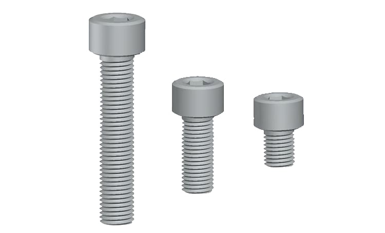
Example of a screw using configurations to have multiple variations of the same part with different lengths.
The ConfigurationManager is used to create, view, and select the multiple configurations in the document. Then you are able to use Design Table Configurations to build the part's or assembly's multiple configurations based on selecting specific parameters. You can also access the Modify Configurations box to modify configurations using commonly configured parameters and manage the configuration data to decide on the size of the files and how much time it will take to save the new configurations.
Setting Configurations
To add a configuration in SolidWorks, pull up the assembly or parts template. Move the pointer over the template as the Configurations option will become displayed. Click the configurations option display for the Configurations dialog box to open. In the box, there will be an option to Add Configurations. Click this option and decide on the name for the specific configuration as you click the OK button.
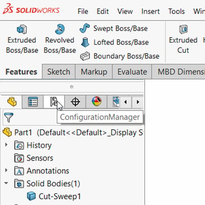
Location of the “Configuration Manager” tab above the feature tree in SolidWorks.
Next, you want to click on the plus + sign to add configuration instances for the parts or assembly. If you have a derived configuration, you click on the added derived configuration after clicking on the existing configuration name. Once done, you can click on the X to exit the Configuration dialog box.
Editing Configurations
To edit configurations, access the desired configuration and pull up the FeaturesManager view. Go into the parts document to modify dimensions, suppress feature states, and perform other options. You can also go into the assembly document to change the component visibility or the suppression state.
If the part needs a change to the configuration properties, go into the ConfigurationManager and select Properties by right-clicking on the configuration name. Use Custom Properties to modify the configuration's custom properties. Then click the green checkmark.
Display Configurations
Another feature in SolidWorks lets you view and sort the configurations. You are able to view the configuration without opening it up, allowing for quick evaluations of parts and assemblies. To view the configuration in PropertyManager, right-click on the configuration in the ConfigurationManager tool and select Show Preview. To hide the preview, just click on the graphics area.
To sort configurations in a specific order, access the ConfigurationManager and go to the top-level configuration. Right-click on the configuration and select the Tree Order function. Various options will be listed that you can choose from to rearrange the sort order: history-based, numeric, manual (drop & drag), and literal.
Summary
SolidWorks is an exceptional 3D modeling tool that engineers use to create different configurations of the same part or assembly by modifying dimensions, parameters, and other aspects of the dataset. It can be used to change the part or assembly in various ways to create components that may need slight changes to be used with different machinery in varying industries. The same part or assembly can have its dimensions manually adjusted to better fit specific machine models. Then the engineer can simulate how that part or assembly works in a virtual setting that emulates real-world applications to ensure that the part or assembly functions as specified.
Key Takeaways
- Configurations streamline part and assembly variations: SolidWorks allows engineers to create multiple versions of a part or assembly within a single file by adjusting dimensions, parameters, or components, saving time and reducing redundant modeling work.
- ConfigurationManager and Design Tables simplify management: The ConfigurationManager tool helps create, view, and select configurations, while Design Tables enable the quick building of configurations based on parameter selections.
- Editing and customizing are flexible: Engineers can easily modify configurations by adjusting dimensions, suppressing features, or changing component visibility, with custom properties available for each configuration.
- Preview and sorting options enhance workflow: Users can preview configurations without opening them and sort them using multiple methods (numeric, manual, and history-based) for improved organization and efficiency.
- Supports design efficiency and real-world validation: Configurations enable quick adaptation of parts for different applications and allow engineers to simulate functionality in various scenarios, improving design accuracy and reducing rework.