


At Epec we work on such a varied and technical catalog of products, so our engineers must be comfortable leveraging every manufacturing technology available to them in order to create solutions in design and production. One of the most important technologies that we use is 3D printing.
This is a flexible and fast technology with accessible startup costs and endless possible applications. We have used this technology in assembly, prototyping, and production for various engineered products. Through our experience with 3D printing, we have come up with five guidelines to follow.
1. Educate Yourself on the Different Technologies and Materials
As a relatively new and rapidly expanding fabrication technique, 3D printing (also known as rapid prototyping or additive manufacturing) employs many different technologies and materials to create parts for numerous applications. Before you embark on the design process with the aim to use 3D printing, it is important to understand the different options you have at your disposal.
The following are some of the most popular 3D printing technologies:
Fused Deposition Modeling (FDM)
Fused deposition modeling is one of the most popular and accessible 3D printing techniques. It has relatively low startup cost and a clean manufacturing process. Like most 3D printing processes, including all three listed in this post, FDM works by splitting a 3D model into numerous 2D cross sections or 'slices'. Each of these slices are then stacked backed up to create a physical approximation of the 3D design.
FDM creates these layers by extruding a small string of molten material through a hot tip. This tip is fed with a reel of this material and will repeatedly lay down the string into the shape of each cross section. Most consumer “desktop” 3D printers use FDM technology.
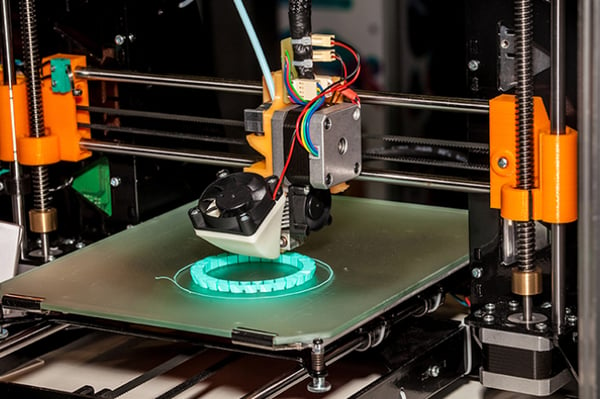
FDM Printer during the printing process.
Selective Laser Sintering (SLS)
Selective laser sintering is another common consumer friendly technology with accessible prices. Like many other 3D printing technologies, SLS will build 3D parts from a stack of 2D cross sections. An SLS machine will lay down a thin layer of powdered material (commonly nylon) evenly across the entire print bed. Then, with a laser, it will sinter the shape of the cross section. After that layer has been sintered, the machine will lay down another layer and repeat the process. After printing, the part may be taken out of the bed and the unused powder shaken off.
SLS printed part. Note the individual layers shown on the curve.
Stereolithography (SLA)
Stereolithography also uses the slice method of building a 3D object. SLA parts are made of a liquid resin that is cured using a light source like a UV laser. A bath is filled with the liquid resin and the build bed is lowered down to the bottom of the bath until it is very close to the bottom. The distance between the bed and the bottom of the bath will be the thickness of the first layer. This layer will be cured into the shape of the first cross section of the object. The bed is then lifted by the thickness of the next layer and the process is repeated. Slowly the object emerges out of the bath pulled up by the print bed.
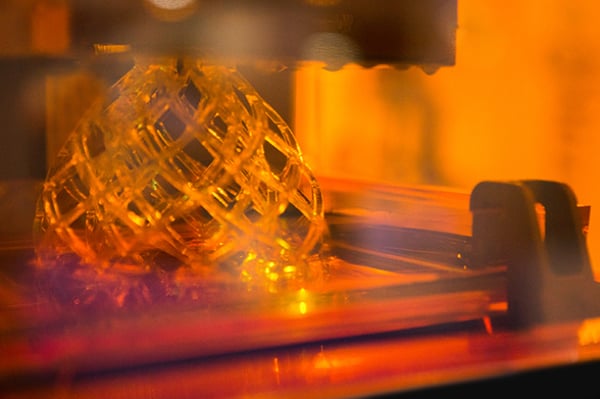
SLA part during the printing process.
2. Take Advantage of Geometries That Aren't Possible Through Traditional Fabrication Methods
Additive manufacturing opens up a world of possibilities when it comes to the geometries that can be achieved versus traditional manufacturing techniques. For example, concerns like adding draft for mold ejection and removing sharp interior corners for CNC milling are non-issues when 3D printing parts. Complex geometries including internal, inaccessible features are possible. This can be helpful when designing fixtures and parts because they can be made using less components and without the need for fasteners which can reduce complexity and decrease assembly time.
3. Consider the Limitations of 3D Printed Parts
3D printing allows for capabilities that aren't available using any other manufacturing technique. However, it also comes with its own unique limitations including the following:
Physical Material Properties
In general, 3D printed parts will be weaker and less robust than equivalent parts made by manufacturing techniques like CNC milling and injection molding. There are several reasons for this, one being the limitations on materials that are available. Though an almost limitless variety of materials is available for 3D printing, the most accessible methods like the three mentioned in this post are mainly available in plastics and resins not metals like aluminum and steel. Beyond the limitations on material availability, the manufacturing techniques themselves can create weaker parts than if made from the equivalent solid material. Because 3D printing involves fusing many different layers on top of each other, each little connection between the layers will limit the strength of the part.
Support Material
Though not limited by the same geometrical constraints as traditional fabrication methods, 3D printing has its own unique geometrical constraints. One being overhangs. Processes like FDM and SLA can't have too steep of an angle of overhang because they would have no solid material to physically print onto and may require support material. Support material is a printed material that is meant to temporarily support the print before being removed from the final product. Processes like SLS don't require support material because the built-up powder in the bed acts as support.
Tolerance
The accuracy and precision of a 3D printed part can't quite match that of traditionally fabricated parts. Much of this has to do with unpredictable shrink and warp due to the heat generated during fabrication. Often there will be a minimum tolerance as well as a per inch tolerance so the larger a feature the grater the potential for a lack of precision. Additionally, with long and thin parts, warp is a risk and parts may come out with an unpredictable curve due to uneven shrink on either side of a part.
4. Use Iteration to Reach a Satisfactory Design
One of the biggest attractions of 3D printing is the low set up costs. Updating and creating new 3D printed parts is relatively quick and inexpensive in a prototyping environment. This has allowed our engineers to introduce a physical model earlier in the design process as there is a very low investment to do so.
This becomes valuable as it allows us to target issues and improve our designs quickly with physical prototypes. With user focused designs that are meant to be handled, this ease of iteration allows to fine-tune the integration of the object with the operation it is intended for. For example, if you are designing an assembly fixture, a 3D printed model can be given to operators who can give their constructive feedback in order to make the design more effective and usable.
5. Explore the Many Applications of 3D Printed Technology
3D printing has many different applications. Though it’s most recognized for prototyping (hence the name rapid prototyping), these technologies can also be used in production parts and fixtures used for assembly. As material selection becomes more varied, engineers can take advantage of more rugged materials with a variety of material properties.
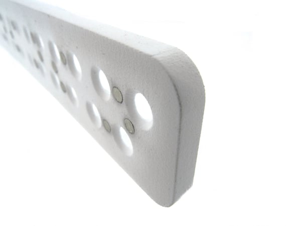
At Epec, 3D printing has become valuable to us in multiple applications. We have employed the use of SLS technology in operator focused assembly fixtures. The technology allowed us to iterate a solution until we found the perfect geometry for our assemblers without the need for a large investment. In addition, we have used SLS to create proof-of-concept prototypes for design updates for custom HMI (Human Machine Interface) enclosures. We have also designed FDM printed parts in electronics tester housings and fixtures for mechanical assembly. The flexibility and capability of 3D printing allows for applications across our multitude of different product lines and manufacturing roles.
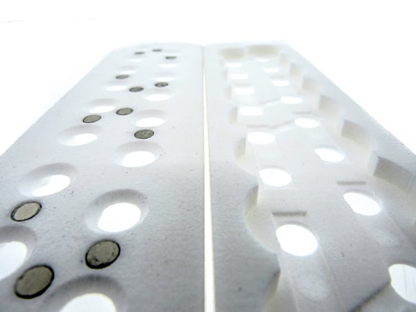
SLS printed assembly fixtures used in our battery manufacturing department. Part on the left shows small neodymium magnets installed to hold small metal components on the reverse side, shown on the right.
Summary
3D printing is an excellent tool in the modern engineer's arsenal. At Epec we have been able to leverage this technology in ways that help our customers get better products faster.
Key Takeaways
- Understand technologies and materials: FDM, SLS, and SLA each have unique processes, costs, and material options, making it important to select the right one for your application.
- Leverage unique geometries: 3D printing allows creation of complex shapes and internal features that are difficult or impossible with traditional manufacturing.
- Account for limitations: Printed parts are often weaker than machined parts, may require support material, and are subject to tolerance and warping issues.
- Use rapid iteration: Low setup costs make 3D printing ideal for prototyping, testing, and refining designs quickly with real user feedback.
- Explore broad applications: Beyond prototyping, 3D printing is effective for fixtures, production parts, and enclosures across many industries when paired with the right materials.
Watch Our Video on 3D Printing
Here at Epec, we use 3D printing to get design concepts and prototypes quickly to customers to reduce their costs and to build tooling fixtures to help build the product faster. Rapid prototyping is a game-changer. With 3D printing, digital designs swiftly transform into physical prototypes. This accelerates the product development cycle, allowing faster iterations and shorter time-to-market.


