


The unique capabilities of flexible circuits allow for additional design elements that are not available in rigid PCB designs. A very common one is integrating Pressure Sensitive Adhesives (PSA) into the design. A PSA is a double-sided adhesive tape that can serve multiple purposes. The PSA is attached to the flex as part of the manufacturing process and the release film is retained on the exposed side to protect the adhesive until it is installed.
PSAs are available in a wide variety of thicknesses and adhesive formulas to meet specific design requirements. Two of the more popular suppliers are 3M and TESA. Between them, there are hundreds of different types of PSAs available.
In this blog, we will review the types of PSAs available, the more common PSA applications, and design considerations.
Mechanical Attachment
Mechanically attaching a flex circuit inside of an enclosure is the most common design requirement in the industry. This allows the flex circuit to be retained in a specific location/shape when installed to prevent damage to the circuit or facilitate further assembly. Instead of having some additional method of retaining the circuit, i.e.: mounting screws, clips, etc. a PSA allows the flex to be a peel-and-stick in-place installation. The PSA can also act as a strain relief if needed.
These PSAs are typically 2-5 mils in thickness and are available in a variety of adhesive formulas depending upon what type of material the flex circuit is going to be adhered to and any other environmental considerations. The most common PSA used in the industry is 3M 467MP, which has a very good bond strength to a wide variety of materials.
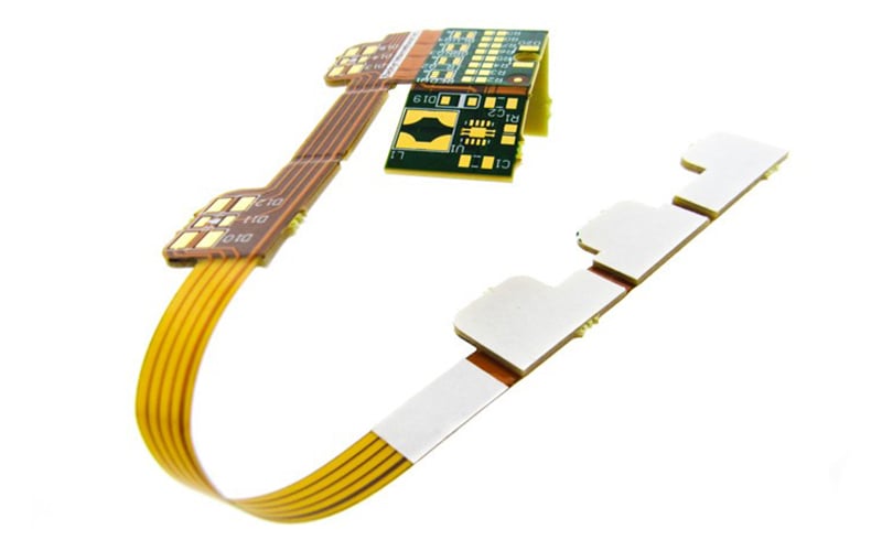
Flexible circuit board with 4 PSA sections.
Folded Flexible Circuit Designs
A unique capability of 1- to 2-layer flexible circuit board designs is that in some applications they can be folded over onto themselves with a virtual zero bend radius. The advantage of this ability is a potentially significant reduction in the flex circuit unit cost.
As an example: Instead of designing in a required “L” shape, which results in very poor material utilization, the flex is designed and manufactured as a straight part, with a very high material utilization, and then folded at a 45-degree angle to create the needed “L” configuration.
A key consideration of this method is that, per IPC 2223 design standard 5.2.4.1, the flex circuit can only be folded once only, and the fold cannot be reopened. The initial fold does not damage the flex but does cause the copper circuits to work harden and lose ductility. It is the unfolding and any subsequent re-folding that will crack the circuitry. Adding a PSA to the fold area is an effective solution to ensure that once the flex is folded it is now bonded to itself and the fold cannot be opened or manipulated in any way.

Heat Dissipation in Flexible Circuits
Flex circuits are often used in applications that generate enough heat that the heat must be dissipated to ensure the operational reliability of the design. For this requirement, there are thermally conductive PSAs available that can be used to either directly attached a heat sink to the flex circuit or to attach the flex circuit directly to a metal enclosure that will act as the heat sink.
The heat sink can be an aluminum stiffener that serves dual purposes of a component area stiffener and the heat sink. The most common application is flex circuit designs that have high-power LEDs attached.
Electrical Grounding
Grounding a flex circuit design to an enclosure can be advantageous in some designs to mitigate EMI interference. This can be accomplished by using an electrically conductive PSA to both electrically and mechanically attach the flex circuit to the metal enclosure. The flexible circuit board design must have an exposed copper ground feature(s) where the PSA is located to allow for the ground connection.
Stiffener Attachment
Stiffeners are used in almost every flex circuit design to either provide support to a component area or meet the thickness requirement of a ZIF connector. For a component area the stiffener material, in most cases, is FR4, and in some cases, where there is a severe thickness restriction, stainless steel.
The preferred method of attaching a stiffener is to use the same adhesive as used to bond coverlays to the flex circuit. The stiffener is then bonded permanently to the circuit under heat and pressure. This lamination process typically requires the stiffener to extend to part of the outline of the circuit. If the stiffener is located within the middle of the design a PSA can be used to attach the stiffener instead. While not as strong a bond as the preferred lamination method, it is still more than a strong enough bond for most applications.
Flex Circuit PSA Design Considerations
PSAs have design requirements, that need to be accommodated, that stem from how the PSA sections are manufactured and installed onto the flex circuit. In general, PSAs are cut to shape as separate entities and then manually positioned and attached to the flex circuit.
The PSA outline is created using either laser cutting, for smaller quantities, or a punch & die set, for larger volumes. The limiting factor will be the size of the PSA. Very small PSA sections can be difficult, if not impossible, to manufacture and handle/position during installation. A review by the flex circuit supplier of the specific PSA requirements is necessary. Laser cutting may also leave a slight blackening at the very edge of the PSA due to the heat generated during the cutting operation.
To aid in the accurate placement of the PSAs it is recommended to add the outline of the PSA sections to the silkscreen layers of the design. If the PSA is used to attach a stiffener, the PSA will be added to the stiffener material first and then the PSA and stiffener outline are cut simultaneously with a routing operation.
The type of PSA used on designs that require automated component assembly and reflow will be limited due to the temperature of the reflow process. There are only a few PSA that are rated to withstand RoHS reflow temperatures. These PSA are limited to mechanical attachment purposes only. We are not aware of any thermally or electrically conductive PSA that reflow temp rated. If needed these PSAs will need to be added to the flex circuit after the component assembly process.
Summary
Adding PSAs to a flexible circuit board design provides additional capabilities that can solve many design challenges ranging from mechanical mounting, heat dissipation, electrical grounding, and cost reduction opportunities.
With such a wide range of options available in both application and materials, we encourage you to contact us to discuss your specific requirements and allow us to provide design support to ensure a successful project.
Key Takeaways
- PSAs provide versatile mounting solutions: They allow for peel-and-stick installation of flex circuits, eliminating the need for screws or clips and even acting as strain relief in some cases.
- Specialized PSAs expand functionality: Options include thermally conductive PSAs for heat dissipation (like attaching to enclosures or heat sinks) and electrically conductive PSAs for grounding to reduce EMI interference.
- They improve folded flex designs: Adding PSAs to folded areas ensures the fold remains secure, preventing re-folding that can crack copper circuits, per IPC 2223 guidelines.
- Stiffener attachment can be simplified: PSAs provide an alternative to traditional heat-and-pressure lamination for stiffeners, particularly when stiffeners are fully internal and do not reach the circuit outline.
- Design and manufacturing considerations are crucial: PSA sections are typically laser-cut or die-cut, require silkscreen outlines for accurate placement, and most cannot withstand high-temperature reflow, meaning some must be applied after assembly.


