


Flex circuits, integral to modern electronics, present unique challenges in their design and application. This blog post delves into the complexities of integrating electrical requirements with mechanical constraints in flex circuit designs. We'll explore various applications, their design considerations, and industry standards, providing a comprehensive view for engineers and designers.
Static vs. Dynamic Applications
In static applications, commonly referred to as "bend to fit" designs, the focus is on balancing flexibility with electrical functionality. Typically, these flexible circuits are recommended to have up to five layers; going beyond this affects the bend capability, crucial for installation and operational functionality. Despite being designed for a single bend to fit into place, these circuits offer a manipulation range of 5 to 10 times. This adaptability is essential for fitting during assembly or for future servicing needs.
Key features of these static designs include controlled impedance for consistent signal integrity, especially important in high-frequency applications. They are also capable of handling higher currents, making them suitable for power-intensive environments.

Additionally, EMI shielding options are often incorporated to protect against electromagnetic interference, ensuring reliable operation in electronically dense settings.
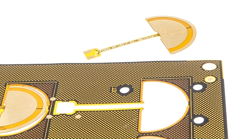
Example of flexible circuit board with shielding layer.
Material selection and layer construction are critical in these designs, balancing mechanical flexibility with electrical performance. This makes static bend-to-fit applications versatile for use in diverse environments like industrial, automotive, and consumer electronics, where reliability and adaptability are key.
Dynamic applications in flex circuit design primarily deal with the challenge of repeated flexing, a critical aspect in many modern electronic devices. A quintessential example of this is the flex ribbon cables found in inkjet printers. These cables are engineered to withstand bending and unbending cycles countless times throughout their use. The unique nature of dynamic applications necessitates a specialized approach to design and materials.
Per IPC (Institute for Printed Circuits) guidelines, dynamic flex circuits are typically limited to 1-layer constructions. This limitation is primarily due to the need for maximum flexibility and endurance under repeated stress. However, there are scenarios where two layers may be necessary. In such cases, the use of thinner materials becomes crucial. Additionally, rolled annealed copper, known for its higher ductility, is necessary to ensure the reliability and life span of the circuit under constant flexing.
One of the primary constraints in the design of dynamic applications is their unsuitability for controlled impedance or high current carrying capabilities. The need for thinness and flexibility often results in designs that cannot accommodate the thickness requirements these features demand. This limitation is a critical consideration when designing for environments where signal integrity or high power transmission is essential.
A notable gap in the IPC standards is the lack of clear guidelines for applications that fall between the extremes of a few bend cycles and those requiring infinite flexibility. For applications where a specific number of bend cycles is expected — whether it's 100 or 10,000 — the IPC standards offer limited guidance. This gap necessitates that designers and engineers engage in in-house testing during prototyping to validate the design. Such testing is vital to ensure that the flex circuit can meet its intended performance criteria over its expected lifecycle.
Minimum Bend Radius: IPC 2223 Standards
The concept of the minimum bend radius is central to flex circuit design, governing how sharply a circuit can be bent without causing damage. The IPC 2223 standards offer crucial guidance in this regard, presenting an estimation formula that plays a pivotal role in design considerations. This formula, rooted in the maximum allowable copper elongation and the material thicknesses involved in the circuit's construction, is a critical tool for engineers. However, its application is not without challenges.
The IPC 2223 formula is known for its complexity, primarily due to the multiple variables it encompasses. These variables include factors like the type of material used, the number of layers in the flex circuit, and the specific application requirements. This complexity often makes the formula cumbersome to use in practical design scenarios, leading many in the industry to rely on established rules of thumb for quicker and more efficient decision-making.
In the realm of static designs, where flex circuits are typically bent once and then installed, the rules of thumb provide a more straightforward approach. For instance, in a one-layer design, the minimum bend radius can be as low as six times the thickness of the flex. As the number of layers increases, so does the required bend radius, ranging from 10 to as much as 35 times the flex thickness for more complex, multi-layer constructions. This scaling of the bend radius with the number of layers is crucial in ensuring the integrity and longevity of the circuit in its final application.
Dynamic designs, which undergo repeated bending throughout their lifecycle, present a different set of considerations. For these applications, the minimum bend radius is typically set at 100 times the flex thickness for a single-layer construction. This extensive radius is necessary to accommodate the continuous stress of bending and unbending, ensuring the circuit's durability. In cases where a two-layer construction is used, this radius further increases, reflecting the added complexity and material involved.
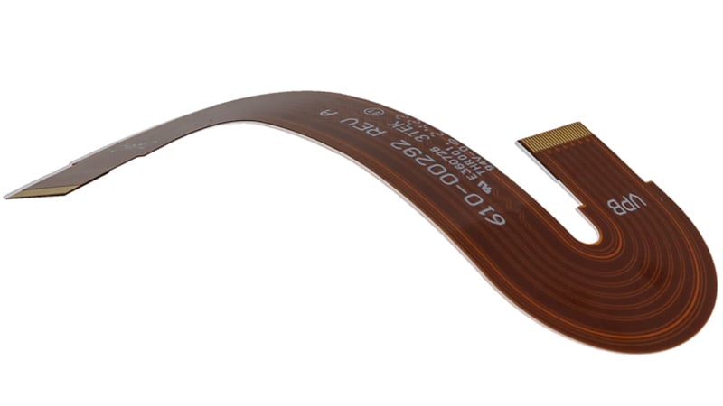
Example of a dynamic flexible circuit design with minimum bend radius.
The concept of the folded flex introduces an entirely different perspective on bend radii. In these designs, the flex circuit is folded back onto itself, effectively creating a zero-bend radius. This method of folding, often accompanied by a crease, allows for a sharp change in the direction of the circuit without the traditional concerns of bending. However, this approach typically restricts the design to one-layer constructions, with two layers being the upper limit, and necessitates careful consideration of material and construction to prevent damage.
Navigating the minimum bend radius in flex circuit design is a complex task, guided by the IPC 2223 standards but often tempered by industry experience and practicality. Whether dealing with static, dynamic, or folded flex designs, understanding and applying these principles is crucial for creating reliable, efficient, and durable flex circuits.
Summary
Flex circuit design is a balancing act between electrical and mechanical requirements. Understanding these nuances is crucial for engineers and designers. Adhering to IPC guidelines and utilizing industry best practices ensures the reliability and functionality of flex circuits in various applications. This guide serves as a starting point for those navigating the complex world of flex circuit design.
Key Takeaways
- Static vs. Dynamic Applications: Static “bend-to-fit” designs support up to five layers with limited flexibility, while dynamic designs typically require single-layer constructions for durability under repeated flexing.
- Material Considerations: Rolled annealed copper is preferred for dynamic circuits due to its ductility, while polyimide layers and shielding options are selected for performance in static environments.
- Design Trade-offs: Dynamic applications cannot typically support controlled impedance or high-current handling, requiring engineers to prioritize flexibility over electrical capacity.
- Minimum Bend Radius: IPC 2223 provides guidance, but industry rules of thumb simplify design: static bends range from 6× to 35× circuit thickness, while dynamic bends require up to 100×.
- Gaps in Standards: IPC lacks clear guidance for mid-range bend cycle applications (e.g., 100–10,000 cycles), making in-house prototyping and testing essential for validation.


