


Dome switches are a very popular solution for use as a momentary switch. They are a good solution that provides tactile feedback that the switch has been depressed and an event registered. Many applications require a dome switch mounted to a flexible circuit board.
These range from large user interface applications with many multiple dome switches to simple 1-3 switches for a space-constrained location in a handheld device. A flex circuit design, or in some extremely complex rigid-flex circuit board designs, allows the complete integration of the design. Any additional connectors or cabling between a rigid PCB and the dome switch area is eliminated thus saving space/weight and additional assembly costs.
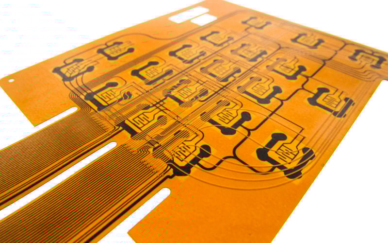
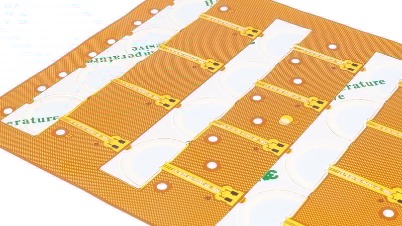
Flexible PCB designed for a user interface using domed switches.

Gerber Layout Requirements
Creating the Gerber data set for a flex PCB applications is straightforward with only a couple of additional considerations. The footprint for the dome switch is defined by the supplier and will vary depending upon the specific switch selected.
A key element is to define the coverlay opening(s) so that the entire footprint is exposed rather than having independent openings for the center and surrounding contacts. This prevents the taller height of the adjacent coverlay from interfering with the operation of the switch ensuring a reliable actuation. Also, having two separate openings is not manufacturable when using a polyimide coverlay vs. a soldermask.
A second element is including the vent hole. This prevents air entrapment which will negatively impact the switch operation/feel and potentially cause the overlay layers to separate from the flex circuit. It is preferred to have the vent hole as a plated hole in a 2-layer flex design. For a 1-layer design, it will be non-plated.
How the flex circuit will be mounted in the assembly and what the sealing “IP” rating requirements are, to prevent the ingress of moisture, dirt, etc., also need to be determined. This will define the amount of spacing required from the edge of the switch footprint to the outline of the flex circuit. 3mm spacing is a typical minimum spacing that will allow the dome switch overlay to seal to the flex circuit and may accommodate and additional sealing methods used in the final enclosure. More space may be required depending upon the application.
Flex Circuit Board Materials
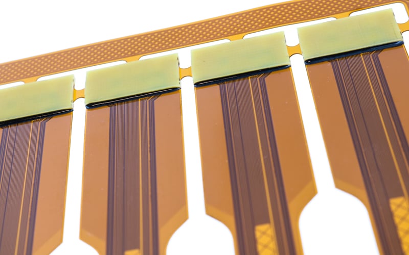
The flex circuit board materials required for a specific design are usually defined by design elements other than that required to meet the dome switch specifications. In most designs, a flex tail is incorporated which then extends out to then into a connector on the control PCB. The bend requirements of this tail area, if excessively tight or convoluted, my require the use of thinner than standard flex materials to reliably meet the minimum bend radius. There are wide variety of materials available. If the tail is to plug into a ZIF connector then an added polyimide stiffener, in the ZIF contact finger area, is required to meet the connector specifications. If the connector is an SMT or PTH male/female header type, then an FR4 stiffener will be needed to support the connector. There is also white and black color coverlays available to meet a cosmetic requirement.
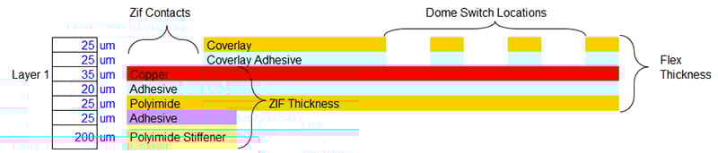
Construction example of a standard 1-layer flex circuit with ZIF contacts.
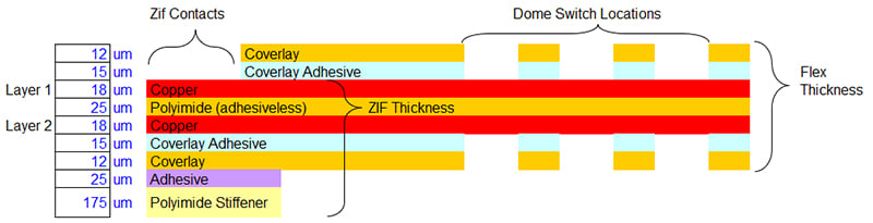
Construction example of a thin 2-layer flex circuit with ZIF contacts .
Surface Finish Requirements
Surface finish requirements will depend upon the application and whether the design also contains components that require soldering. The application considerations are the degree of reliability required for the application, the number of cycles the dome switches will experience during the life of the product, and if the electronics are sensitive to the contact resistance of the actuated dome switch.
The three standard finish options are:
- Nickel Plating: 50-200 uIN for <1 million cycles and 200 -500 uIN for > 1 million cycles with no contact resistance requirements. Please note this surface finish does not meet the requirements of ZIF connectors and does not allow for component soldering. This surface finish is seldomly used.
- Hard Gold: 15-30 uIN for <1 million cycles and 30 -50 uIN for > 1 million cycles with low contact resistance requirements. Both thickness ranges meet ZIF connector requirements. However, if component soldering is required then 15uIN hard gold is recommended to prevent the formation of brittle solder joints.
- ENIG (Electroless Nickel Immersion Gold): 100-200 uIN Nickel + 3-5 uIN gold. Low cycle life requirements. Meets most ZIF connector requirements. Allows for all component soldering. Not used in high-reliability applications. Additional testing may be required to ensure the finished part meets the number of cycles required.
Stiffener & PSA Requirements
Many flex circuits with dome switches require additional stiffeners or PSAs, pressure-sensitive adhesives. An additional stiffener(s) may be necessary to provide support for the force applied when actuating a dome switch if the enclosure is not configured to do so. These stiffeners would reside behind the switch area and be thick enough, 1mm - 1.5 mm, so as not to allow any deflection.
PSAs are also commonly spec’d to allow for ease of attachment to the enclosure. The PSA again resides behind the switch area and can be used in conjunction with a stiffener if a specific thickness is required to fit the enclosure. The most common PSAs used are 3M 467 for flex circuits that do not have any component assembly and 3M 9077 for designs that require SMT assembly. Other adhesives are also available for unique requirements.
Flex circuit board with stiffeners.
Flex circuit board with PSA.
Summary
Applications for flex circuits boards incorporating dome switches are extremely common throughout our industry. The combination allows for reduced space requirements and design flexibility in many handheld devices.
The design process is not overly complex but does have several elements that need to be evaluated and incorporated to ensure a successful design. At Epec can support a dome switch project by providing complete or partial design services as part of our user interface product line. Please feel free to contact Epec if you have any questions or require design support in developing a dome-switch-based flex circuit.
Key Takeaways
- Gerber layout must account for dome operation: The coverlay opening should fully expose the switch footprint and include vent holes to prevent air entrapment and overlay separation.
- Material selection depends on design needs: Tail bend requirements, connector type, and cosmetic preferences (such as black or white coverlay) determine the best flex materials and stiffeners.
- Surface finish impacts durability and function: Nickel plating, hard gold, and ENIG each have different suitability for cycle life, contact resistance, ZIF compatibility, and soldering needs.
- Stiffeners and PSAs provide support and mounting: Stiffeners prevent flex deflection under actuation, while pressure-sensitive adhesives allow secure attachment and can be tailored to enclosure thickness.
- Flex with dome switches offers efficiency: Integrating switches into flex or rigid-flex designs reduces space, weight, and assembly costs while supporting reliability in handheld and interface devices.


