


The process of extruding metals, plastics, and other molten materials is common and necessary to produce many of the products used in the world today. Items such as drinking straws, PVC pipes, and even coat hangers also rely on extruded raw materials for processing. No different than a child’s playdough set or making homemade pasta, material is forced through an extruder die creating the long uninterrupted shape of whatever material is being made.
Much of the extrusion process is performed with long runs of wire, consuming hundreds of feet to prime the machinery. The setup process and scrap make it impractical to produce small runs of wire. Batches of 500 feet or more are necessary to justify the cost for custom runs. It takes time and material to warm up the equipment, dial-in the process, and verify that the finished cable assembly meets all electrical and dimensional requirements.

These complex extrusion processes are necessary to produce much of the world’s electrical cable. Whether it’s the extension cord used to power your holiday lights, the Cat5e cable used to connect to the internet, or the USB cable used to charge your smartphone, extruded cables are everywhere. Surprisingly, when built with standard materials and cross sections, customized UL-approved cables can be fabricated in less than three weeks for a relatively low price point.
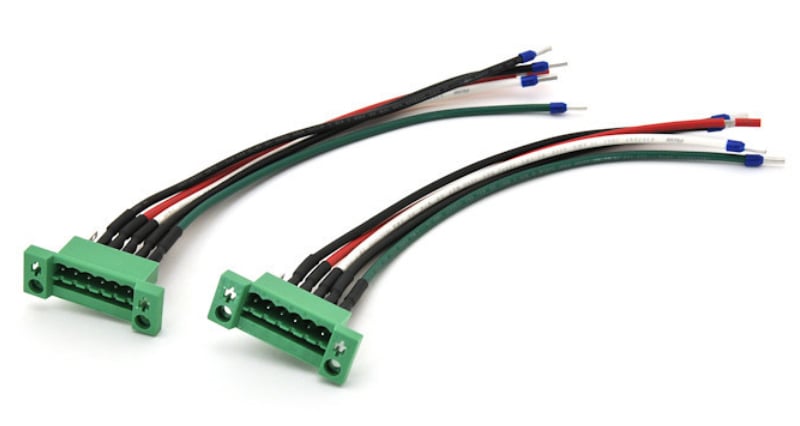
Cable assembly with single conductor wires: black, red, white, and green.
Single Conductor Cables
The simplest wire extrusion is the single conductor wire. Consisting of a single copper center conductor, this flexible wire is jacketed with thermoplastic insulation and wound onto various sizes of spools. This wire type can be used as a single discrete wire all by itself, such as in a ground wire or the positive leg of a low-voltage system. Alternatively, numerous single conductor wires can be bundled with other single conductor wires to form a more complex cable harness. Jacket colors can be varied with about a dozen standard colors to choose from. It’s common for each wire within the cable assembly to carry a unique electrical signal- usually power or data, with each having its own dedicated jacket color. Color coding each wire jacket helps identify the cable’s pinout, making assembly and electrical testing easier for technicians.
Using single conductor wires helps reduce the bulkiness of the complete cable assembly and can improve their overall flexibility. Bundles of single conductor wires can be fanned out making cable routing and navigating tight spaces easier for assembly workers. Since a wire’s minimum bend radius is a function of its diameter, the smaller the diameter the more flexible the wire is. Additionally, since there is no outer jacketing layer on a single conductor wire when compared to a multi-conductor cable, single conductor wires have a tighter minimum bend radius which further increases their flexibility.
While highly flexible, single conductor wires only have one layer of insulation which can limit their abrasion resistance making them prone to damage in harsh environments. Single conductor wires also need shielding to be used in areas that are susceptible to electrical noise. Single conductor wires are appropriate for prototyping and development, but if high levels of radiated emissions or rough handling are expected, a shielded multi-conductor cable is likely the better option.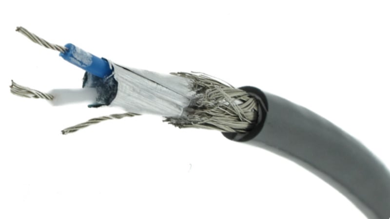
Cross section of a shielded multi-conductor cable.
Multi-Conductor Cables
By definition, a multi-conductor cable consists of several single conductor cables. But it’s the specific conductor sizes, the shielding, and the combination of each that allows multi-conductor cables to be used in so many design applications. Specialty multi-conductor schemes like USB and Cat5e include shielding and twisted pairs that enable the wire to meet standardized data transfer rates. Using this same design principle, differential and twisted pairs can be included in a customized cable bundle that provides both power and data. As long as order minimums are met, custom extruded UL-approved wire is an option that can actually reduce cost and lead-time.
UL ratings are common for various types of single and multi-conductor cables. These UL-approved single wires include UL1061, UL1569, and UL1015 and are designed to meet temperatures of 105°C at operating voltages in excess of 300VDC. These single conductor wires can be bundled and jacketed using an additional extrusion process creating a UL-approved multi-conductor cable. Some of the most common UL-listed multi-conductor cables include UL2464, UL2517, and UL2725.
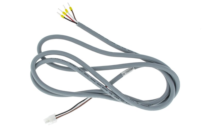
18AWG multi-conductor cable conforming to UL2464.
Considerations for Custom Multi-Conductor Cables
For specific projects where thousands of linear feet of cable will be consumed, a custom multi-conductor cable bundle can offer several benefits. One of the primary benefits is that several cable legs can be consolidated in to one main cable trunk. For example, instead of running a pair of 12AWG wires for primary power, and a second pair of 26AWG wires for low voltage, both can be collocated into a UL-approved cable bundle conforming to UL2517. This wire type can be produced in 3 weeks, and ships either spooled or assembled with all existing certifications conforming to the applicable UL rating.
Another benefit of using a custom multi-conductor cable is that the exact placement of shielding, drain wires, and twisted pairs can be completely customized to a particular design requirement. The wire size, jacket color, cable lay, and even the shielding type can all be configured for the precise number of circuits needed. The wire size and shielding scheme for each twisted pair can be further customized allowing for any combination of shielded twisted pairs. For example, 28AWG shielded pairs and 24AWG unshielded pairs can be bundled alongside larger current-carrying wires, such as 12AWG red and black power leads.
Custom multi-conductor cables can be developed to include any combination of shielding provisions necessary to meet the desired program objectives. Shielding effectiveness is a function of the type of shielding used, the percent coverage, and the number of layers or “shields” used within the bundle. The example cross section below portrays a cable bundle with 10 total 26AWG twisted pairs. This design includes an overall foil shield, a single drain wire, and a tinned copper overbraid that bundles all conductors and shields. The last extrusion step produces the thermoplastic outer insulating jacket giving the cable its final gray or black look and smooth plasticky feel. The exact shielding effectiveness of this cable type will vary based on the details of the cross section, but comparable wire bundles have been certified to medical, military, and aerospace levels of radiated emissions and radiated susceptibility EMI testing.
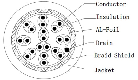
Cable bundle with 10 total 26AWG twisted pairs cross section diagram.
Getting Started
The first step in launching any custom cable extrusion is to carefully define the wire size, the conductor count, and the shielding methodology. Sourcing just 50 feet through the distribution of a similar multi-conductor cable may be enough material to help build prototypes and verify that the wire harness design is satisfactory.
Once confidence is gained that the design is functional, planners can begin to push for quotes of custom cable extrusions. Full-service manufacturing partners like Epec can help with the design for manufacturability review, fabricating the custom cable extrusion, terminating the final cable, and performing the necessary electrical tests to show compliance to program objectives.
Summary
When in a bind, knowing that stringing together a group of single conductor wires and bundling them with a few wire ties can help prove the function of a multi-conductor cable. This approach may also prove that a customized shielded cable is necessary for the system to operate. Like most rapidly emerging development projects, early engagement with a full-service manufacturing partner like Epec can be the difference between meeting program milestones and missing schedule commitments.
Key Takeaways
- Extrusion is essential for custom cable production at scale: Because of the material priming and setup involved, custom cable extrusions typically require minimum runs of 500+ feet to be cost-effective, making them ideal for larger-scale applications.
- Single-conductor wires offer flexibility and simplicity: These cables are great for prototyping and tight spaces, thanks to their small diameter and bend radius. However, they lack shielding and abrasion resistance, limiting their use in harsh or noisy environments.
- Multi-conductor cables bring structure, shielding, and signal clarity: With customized shielding, twisted pairs, and conductor sizing, multi-conductor cables can combine power and data in one protected bundle, critical for complex or EMI-sensitive systems.
- UL-approved options are widely available for custom runs: UL-rated single and multi-conductor cables (like UL2517 and UL2464) can be produced in as little as three weeks and offer both electrical performance and regulatory compliance out of the box.
- Early collaboration with manufacturers ensures efficiency: Working with a full-service cable assembly partner like Epec allows you to fine-tune designs, consolidate assemblies, reduce cost, and meet tight production schedules with confidence.


