


We get many inquiries from our customer base regarding updating or converting an existing design from its current configuration of rigid printed circuit boards interconnected with a wiring harness to a rigid-flex printed circuit board. With our experience, we can quickly determine if a conversion option is worth investigating further. We can also see how some are relatively obvious that they would need a complete redesign to convert.
There are multiple reasons why a conversion should be investigated to ultimately determine the best solution for a given design. In general, with some exceptions, a flex circuit board can always be utilized. The exceptions are typically where a flex-based solution does not improve the design but only adds cost.

For existing designs, a conversion from wiring to flex circuit for most cases will require a redesign of the rigid PCB to incorporate the flex circuit. Only on the rare occasion, where headers are currently being used, a connector may be available for the flex circuit that will allow a direct plugin replacement.
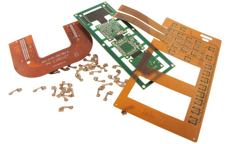
Example of various flex and rigid-flex circuit boards.
Why Convert a Design?
The three main reasons we see for converting a design are:
- Cost Reduction
- Design Improvement/Requirements
- Functionality
- Reliability
- Ease of assembly
- Reduced packaging size
- Wired Solution (used for proof of concept only)
For some applications, a flex circuit conversion can be justified exclusively through the cost reduction that can be achieved. These are usually designs that have a significant number of interconnects between rigid PCBs, which results in complex and cumbersome wiring harnesses. These harnesses will have to be hand assembled and then attached to the rigid circuit boards. This can be with connectors, which tend to be bulky and consume a lot of space, or directly soldered to the PCB. In either case, there is a significant amount of manual assembly required.
Converting to a flex-based solution either eliminates any additional manual assembly or makes it a very simple and quick flex circuit plug-in operation. A key element in making this cost-based conversion decision is adding up “all” the costs incurred by the wired solution. In most cases comparing material costs alone will usually favor the wired solution but once assembly labor costs are included the flex-based solution results in the cost reduction. A lesser benefit is the simplification of the bill of materials for the design.
Deciding to convert for design improvements or requirement reasons is more involved as there are now design elements that need to be reviewed and addressed beyond cost alone. In many cases, a design starts off as a wired solution to prove the concept. Once achieved there are additional design elements that need to be resolved that indicate that a wired solution may not be the optimum solution. Some of these requirements are:
- Packaging: Wiring won’t fit or easily fit in the required package size.
- Performance: Wires don’t meet Controlled Impedance or EMI requirements.
- Reliability: Added points of interconnect and mass of wired solution negatively impact reliability.
A flex-based solution easily addresses all the above. Flex circuits consume approximately 10% of the space of wiring, have much tighter bend capabilities, meet all impedance/EMI shielding requirements, improve reliability by reducing the number of points interconnect (potential failure points) and reduce mass by up to 80% for shock and vibration requirements.
Evolving a proof of concept only design to a flex-based solution is the same as the previous section with the added advantage of starting a new design. All the design elements can be evaluated, and the most appropriate flex-based solution can be applied.
Common Flex-Based Options
Three of the most common flex-based options available for investigation (in order of cost structure) are:
- Rigid PCBs & Flex Circuit
- Flex & Stiffeners
- Rigid-Flex
Which option is best suited depends upon several variables:
- Layer count of the existing rigid circuit board design
- Connector types required
- Size and shape of the complete unit
- Performance requirements, impedance, EMI, current, etc.
- Number of interconnects
Each solution has its own capabilities and strengths. Flex circuit technology has a very wide range of available configurations which makes the most capable interconnect solution.
Rigid PCB and Flex Circuit
This is a viable solution for many applications. Of the two methods, it is usually the most cost-effective. The cost of the rigid PCBs remains as is, which is at a lower price point per square inch than either flex or rigid-flex. The flex circuit board, as a separate part, is then connected to the rigid PCB. If vertical spacing is limited, then the flex circuit can be directly soldered to the PCB. There are different connectors available depending on your specific design needs.
The most common and popular flex connector is ZIF connectors. They have the advantage of being a very cost-effective one-part connector system that requires no connector assembly on the flex circuit. The flex plugs in directly into the ZIF connector. ZIF connectors are available for a wide range of applications, I.E.: Controlled impedance, EMI shielding, mechanical retention tabs (for high-reliability applications), etc.
Beyond ZIF connectors any other connector systems that can be soldered to a rigid PCB can be attached to a flex circuit. The limitation of this method is that rigid PCB real estate is consumed by the ZIF connectors, and the flex circuit is typically limited to 3 layers of circuitry or less.
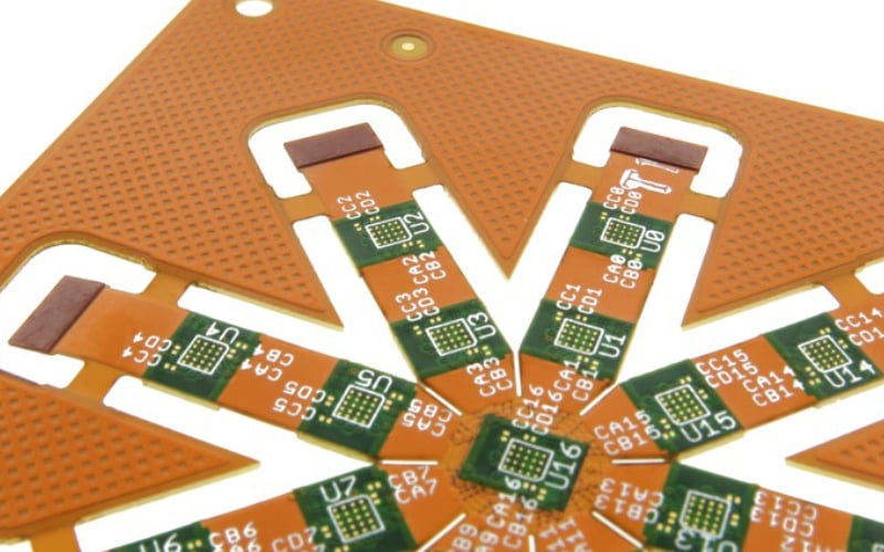
Example of flexible circuit board with stiffeners.
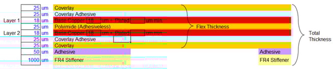
Flex circuit layers and stiffeners construction example.
Rigid-Flex Circuit Board
The rigid-flex circuit board option is fully integrated where the flex layers are laminated within the rigid areas. No additional connectors are required. This method has the highest capabilities but is also the most expensive solution.
Rigid PCB real estate is freed up, potentially allowing for a smaller rigid area. Higher flex layer counts are available, allowing for a very high number of interconnects between rigid areas. Controlled impedance and EMI requirements are easily achieved. SMT components can be mounted on both sides of the rigid areas. This solution is typically applied where it is known in advance that the wired proof of concept was not going to meet the packing requirements of the final assembly.
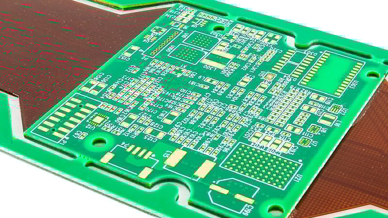
Example of a rigid-flex printed circuit board.
Flex circuit layers and stiffeners construction example.
Summary
How to convert an existing design to a flex-based circuit board is a common question asked by our customer base. In most cases, our customers do not have the complete knowledge to effectively make the decision as to whether to proceed or not. Our customers have a belief or question that there is a potentially better solution to either improve their design or address challenges/problems that they are experiencing with their current wired configuration. In many applications it is worth investigating a flex-based solution to quantify the extent of the improvement possible be it cost, performance or reliability-based.
Key Takeaways
- Converting to rigid-flex PCBs: Reduces cost by eliminating labor-intensive wire harness assembly and simplifying the bill of materials.
- Flex circuits improve performance and reliability: Flexible PCBs offer controlled impedance, EMI shielding, and fewer failure points compared to wired interconnects.
- Packaging efficiency: This is a major advantage, since flex circuits can reduce interconnect space requirements by up to 90% and mass by as much as 80%.
- Design options vary by application: Common solutions include rigid + flex, flex with stiffeners, or fully integrated rigid-flex, each balancing cost and capability.
- Best candidates for conversion: Designs with multiple interconnects, tight packaging requirements, or proof-of-concept wired builds that must evolve into production-ready solutions.


