


Flex circuits have the capability of utilizing a wide variety of connector options. The list, with a couple of exceptions, includes all connector systems that can be used on rigid printed circuit boards (PCBs) plus a couple of additional systems that were specifically designed for interconnecting flexible circuits to rigid PCBs or wiring harnesses.
The best connector system for a specific flexible circuit design will depend upon several factors. Some of which are: the number of interconnects, available spacing / real estate on the rigid PCB, signal integrity requirements, current-carrying requirements, retention requirements, etc.
In this blog, we’ll review which are the most commonly used/popular connector systems for integrating a flex PCB design into a final assembly.

Zero Insertion Force (ZIF) Connectors
ZIF connectors are by far the most used interconnect system between a flexible circuit and a rigid PCB or another flex circuit. The ZIF connector was specifically designed to take advantage of flex circuit design capabilities and meets a wide range of signal requirements. These range from standard low-level signals to high-speed controlled impedance and higher current carrying requirements.
A ZIF connection can best be described as a 1-part connection system. The ZIF connector is the female portion, which is soldered to the rigid PCB. The flex circuit itself is the male portion which plugs into the ZIF connector. This method has several advantages over other connector systems:
- Lower cost - there is only one connector to purchase and assemble.
- Reliability - reduced points of interconnect (no additional connector solder joints on flex circuit) and locking/high retention force designs.
- Wide range of capabilities like controlled impedance or higher current carrying capability.
- High density/small form factor - variety of finger spacing and ZIF connector form factors available.
Designing a ZIF flex circuit connector is a straightforward process by following the specific ZIF connector specifications. The common design elements are contact finger sizing, finger to part outline spacing, contact area outline sizing, and contact supporting stiffener dimensions. We recommend to our customers to include the product number of the ZIF connector in the fabrication drawing. This allows the design to be confirmed as an error in any of these elements will negatively impact the performance.
In the early stages of ZIF connector development, reliability may have been a concern due to the method used to retain the flex circuit within the connector. These early designs, which are still available, use a wedge-based system, which compresses the flex circuit within the connector to provide both the contact force for the electrical contacts and a friction force to prevent the flex from falling or pulling out of the connector. Assembly requires the wedge lock connector to be extended out, the flex inserted to full depth and the wedge lock pressed back in. Reliability issues could arise from partial insertion of the flex, incomplete closure of the wedge lock or excessive force applied to the flex which can pull the flex out of the connector.
More recent designs addressed all the reliability issues by utilizing a system with a hinged locking lid in the connector and retention tabs designed into the flex outline. With this method the hinged lid is opened, the flex is dropped into the connector and the lid snapped shut. The flex engages fully, due to the positioning of the retention tabs and the force required to pull the flex out is significantly higher. The retention tabs need to be physically ripped out of the flex to allow it to be pulled out, which requires a large amount of force. The result is this type of ZIF system is being used in high-reliability designs.
ZIF connectors are available that meet controlled impedance requirements and higher current levels are achieved by using multiple contacts. A common max. current per contact for a ZIF connector is 500 mA (2 contacts = 1 amp etc.).
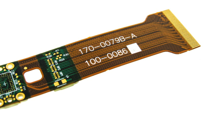
Flexible circuit with ZIF connectors.
Male/Female Header Systems
I can’t identify any exceptions that a connector system that can be attached to a rigid PCB can also be used on a flexible circuit. The flex circuit, no matter the layer count, is designed with a localized supporting stiffener, usually FR4, which supports the connector. This applies to either SMT or PTH-style systems. The difference between the two is to which side of the flex the stiffener is permanently bonded.
For SMT connectors, the stiffener is attached to the opposite side of the flex in the connector area. The parts are supplied in a traditional array form for assembly through a standard pick and place process.
For PTH connectors, the stiffener is attached to the side from which the connector is inserted. The stiffener will have slightly oversized clearance holes which allow the PTH pins to pass through and then engage into the flex circuit. The PTH pins are then accessible for soldering on the opposite side of the flex circuit.
FR4 stiffeners are available in a wide range of thicknesses to meet support requirements and or space limitations. The low end is 0.010” and the common high end is 0.059”, which replicates a standard rigid PCB. Thinner stainless steel stiffeners are available if space limits the thickness, but a high level of support is required.
The advantages of standard male/female connector systems are:
- Higher interconnect requirements - greater than 40 signals.
- Very high current carrying requirements - greater than 3- 4 amps.
- Hard locked screw-based connector retention - high reliability/shock and vibe applications.
- Retrofit to existing designs.
- Custom configured connectors are available for unique applications - high-speed signal combined with high current etc.
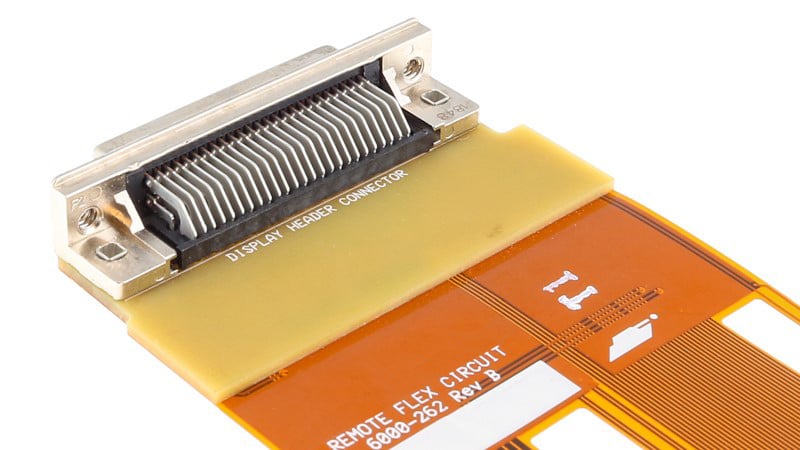
Male/female connector on a flexible PCB.
Crimp Contacts
Crimp contact connector systems are an offshoot of crimped wire connectors. They are not very commonly used in today’s modern designs. These systems allow flex circuits to be easily connected to wire harnesses. The flex is designed to accept contacts that are mechanically crimped through the contact pads on the flex circuit. A housing is then installed over the contacts providing an easy plug in with a mating connector on the wire harness.
The advantages of this method are:
- Easy of assembly: The contact crimping on the flex is an automated process that crimps all contacts simultaneously.
- Wire harness side connector and assembly is standard technology.
- Eliminates the need for any interface rigid board to bridge wiring harness to standard male/female or ZIF connector systems.
Interposer Connectors
Interposers are a unique subset of the connector industry. These systems are usually used in applications with very high point counts of 300 or higher. The interposer is mechanically clamped between the flex circuit and rigid PCB with a supporting clamping plate which is then locked together. The clamping plates are required to apply and distribute the required compression force evenly across the area of the interposer. While these systems can be expensive, they do offer the following advantages:
- Very high pin counts that cannot be achieved with any other connector system.
- Easy of assembly: mechanical compression/solderless connection with connectors located with tooling pins and screwed together.
- High reliability due to positive clamping system for designs with shock and vibe requirements.
- Custom connector geometries and point counts.
Summary
ZIF connectors are by far the most commonly used and most cost-effective method of connecting a flex circuit to a rigid PCB or another flex circuit throughout all segments of the electronics industry. While ZIFs do meet a very wide variety of requirements, they cannot meet all interconnect needs. Flex circuit technology allows for any type of connector system to be used to meet a design’s specific/unique requirements.
Key Takeaways
- Flexible circuits can use nearly any connector system, from ZIF connectors to male/female headers, interposers, and crimp contacts, depending on the design needs.
- ZIF connectors are the most popular choice for flex circuits, offering cost efficiency, high density, and reliable connections with simplified assembly.
- Male/female header systems are ideal for high-current or high-pin-count applications, providing robust retention and compatibility with existing rigid PCB designs.
- Interposer connectors excel in very high pin count applications, offering solderless, mechanically clamped connections that improve reliability in shock and vibration environments.
- Connector selection depends on multiple factors, including interconnect count, available space, current requirements, and retention needs, making early design planning critical for successful integration.


