Typically, constraints are not something a designer wants to incorporate into a new project when first getting started on a new product. When you hear “constraint”, the first word that may come to mind could be “limitation”. Generally speaking, that word association is accurate, however, when dealing with CAD software it is not necessarily a negative thing.
Constraints within CAD modeling act more as a defense for your project rather than a detriment. When modeling/sketching without constraints, the smallest change to any detail could throw the whole project out of order, and in some cases, what was intended to be a small change turns into a complete restart.

SolidWorks Constraining Sketch
Before you can have a CAD model completed, you need to first have some sketches to create the 3D geometry. Once the two-dimensional shape is established, it is critical that the sketch then be constrained.
To constrain the sketch, you either add dimensions to the shape or add relations to specific details of the sketch. Say, for example, you need a hard right-angle corner in your design. You can either dimension the lines to be 90 degrees apart, or you can relate one line perpendicular to the other.
Once fully constrained, the sketch itself should have some way of showing that the sketch is fully constrained. In SolidWorks for example, unconstrained lines appear blue; when fully constrained, the lines turn black. Ideally, you want your entire sketch to appear black, that way you know for sure that your sketch is fully constrained, and nothing the user does further can alter the shape without first removing established constraints.
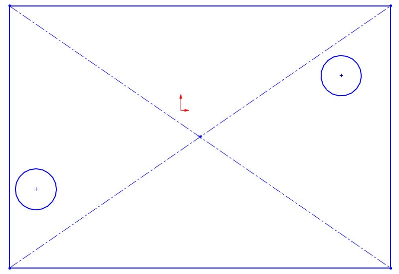 Example of an unconstrained sketch.
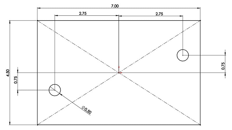
Example of a fully constrained sketch.
Assembly Constraining
Constraining CAD assemblies is essentially the same thing as constraining a sketch: the whole point is that you want to lock the design in place. Unlike sketches, there is very little to visually tell you that your assembly model is fully constrained. You know your model is unconstrained if you can move components of the assembly around freely.
The way you constrain an assembly in SolidWorks is to apply “mates” to the various components of the assembly. There are many mate options within SolidWorks, from basic “coincident” and “concentric” mates to more advanced motion limiting and path mates. The basic mates will allow you to fix two surfaces together or align a circular feature to a corresponding circular hole. You can still fully constrain an assembly model and still allow it to move; that is where the advanced mates come into play.
Imagine the mechanism of a windshield wiper; the arms of the wipers move but only along a fixed, continuous path. You can model this movement with CAD using assembly mates. Accurately mating assembly components is vital if you want to verify that your assembly model will operate/move as intended. Assembly/sketch constraints are an important tool for successful and efficient CAD modeling. Without them, a simple update can turn into a massive rebuild.
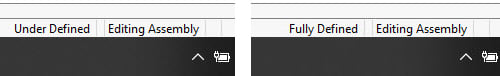
An unconstrained assembly (left) vs. a fully constrained assembly.
Attention to Detail
So why take the time to make sure all sketches/assembly components are fully constrained? If the model is built, and everything looks good as built, what is to stop me from moving ahead with getting my part/assembly manufactured?
The short answer is nothing; you can absolutely move forward down that path. It does, however, open your project up to a lot of risk down the line. For example, if you have a part that has multiple drill holes, and the drill hole locations are critical to the part’s design, it is vital that the hole locations are fully constrained. If they are not, and a few years into the part’s life it is determined the holes need to be moved, moving the hole locations can either be a quick edit or a lengthy process. If the holes were fully constrained, you should only need to move one hole, and depending how you modeled the part, the rest of the holes will follow suit. If the hole locations were not constrained, you could find yourself re-positioning each individual hole which can be very tedious.
What if you have a part with very complex geometry? You may know what you want to change about the part, however more than likely your CAD software does not. If you input a dimensional change to an unconstrained sketch, the CAD software may apply the change in a way that completely turns the sketch geometry inside out; this has happened to me! Were the sketch constrained, there would only be one, maybe two ways to apply the edit per the software’s code, ensuring the update is applied the way you envisioned in your mind’s eye. To wrap up this section, properly constraining sketches/assemblies is the best tool for protecting your work from slow-downs or repeated modeling steps.
Summary
In the manufacturing world time is money, so you definitely do not want to waste time fixing work that has already been completed. When it comes to CAD topics, constraining your work is the best method for preventing repeat work.
The last thing you want to do when making a simple edit to an established part is to be faced with having to completely re-build the part from scratch. Leaving your work unconstrained leaves the door open for just such an eventuality. Much like saving a long Word document as you write it, be sure to constrain your CAD models as you build them as it will save you time and frustration in the long run.
Key Takeaways
- Constraints protect your design from unwanted changes: In CAD modeling, constraints are safeguards that prevent sketches or assemblies from shifting unintentionally. Without constraints, even a small change can distort your model and require rework or a full rebuild.
- Fully constrained sketches are more stable and reliable: In SolidWorks, fully constrained sketches turn black, indicating that all lines and points are locked by dimensions or relations. This ensures the geometry behaves predictably when edits are made.
- Assemblies use mates to define relationships between components: Just like sketches, assemblies can be constrained using mates (e.g., coincident, concentric, motion-limiting). These mates define how parts interact and ensure proper mechanical movement or fixed positioning.
- Proper constraints save time in future design changes: If a design change is required, constrained features (like holes or cutouts) will update predictably and automatically. Without constraints, updates can lead to tedious manual repositioning and increased risk of errors.
- Constrain as you build to prevent costly mistakes: Constraining sketches and assemblies during initial design protects your project from becoming unstable later. It’s a time-saving habit that reduces errors, supports consistent revisions, and enhances design efficiency.