


I love looking at data. Sounds weird, right? I guess it is because I have been working in the industry for so many years. I have seen the technology changes, and I just find it fascinating. In this blog post, we will recap the past, which some of the time creeps its way back to Epec, the present, and the future of printed circuit boards (PCBs).
Let’s get to it.

PCB Data Packages
We can’t change history. It is what it is and hopefully the parts that were bad don’t repeat themselves. In the land of printed circuit board manufacturing, the past has a way of creeping back in or repeating itself.
So, let’s talk about the past and how it blends with the here and now. It is true that technology has come a long way, but some designs, believe it or not, have been around forever. When I think of the big PCB customers from my first years in manufacturing, in the early 1980s, I think of Texas Instruments, IBM, Simplex, and Welch Allyn. Not the most difficult technology compared to what we see today, but at the time, they were the up-and-coming leaders, in my opinion.
Data, the circuitry, was hand carried or shipped either on a floppy disk or a diskette, or silver mylars, rolled up in a tube or in a manilla envelope. Yes, that is some temperature/humidity controls there. They were sent overnight or spent several nights in the mail or in a vehicle, the perfect way to start off manufacturing a PCB, out of control. We loved the floppy or disk, clean electronic data to pass through our new CAM software and plot first generation films. Contact films, negative to positive, hand cutting and trimming, registering to a drilled piece of laminate, it could take weeks to complete this process. Not to mention keeping the line widths, spacing, scale; it was a full-time job for many.
We don’t typically see the floppy or diskette anymore, but we have seen our share of silver films, so don’t lose hope on the past there is a way forward. Typically, we see mostly 2-layer PCBs, no SMTs, 1-side soldermask used for both sides, and a legend or silkscreen. Epec provides scanning services to generate electronic files and extract a drill data when possible; it is a process that takes a few days. We will perform a full DFM on the data set, feed information to you, and work through an approval process with you to be sure everything is accurate. We also scan and create files from raw unassembled PCBs, 2-layers only, and it is a verification approval process but still possible.
I can still hear the pinging and squealing of the modem as our first electronically transferred zip files came into the building. Computer-generated files were a step towards the future. We reluctantly embraced the technology knowing jobs would be changing or lost with this new better, faster process.
Gerber files, data with apertures, manual input required with plenty of room for error. Coding in all those shapes and sizes and following station codes makes my head spin. RS274-D was better format, but still required some manual input and left room for error. RS247X, the complete auto import dataset, easily interpreted buy smart CAM software and certainly made life easier for all. The RS274 formats brought us into the present opening doors to begin pushing the limits of manufacturing to where we are today. ODB++, the all-inclusive soup-to-nuts software, is probably the best format to receive. It includes all the files predetermined in the correct format, drill, and non-copper layer labeling as well as a netlist.
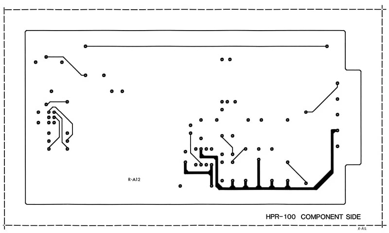
Example of old technology PCB layout where the features were drawn/made with red transparent tape and donut dots. The file as shown would be scanned or photographed from a mylar film to create films for production.
What data Is Needed in the PCB Data Sets
The present: data is data no matter what the format is; we have to use it if we want to produce the parts. All types of data will allow for processing the tools to manufacture a PCB, and it is standard no matter what you need the files to make. But what is needed for the build?
Let’s break down the incoming .zip file by its content. The first item we will cover is the NC Drill program for a computer numerical control (CNC) system used for drilling and profile routing the PCB. Excellon is the most commonly used drill format or program. X and Y coordinates feed into the CNC, allowing for the hole to be drilled in its appropriate location. Typically, there is an individual tool code for each size. Providing a drill chart containing the desired finished hole size, a conjoining symbol, the quantity of each and a map of the location or lay out is needed for inspection during processing.
Next, the outline. A 1-to-1 outline shows the exact edge required for the PCB and what the boards shape and size is, including any cutouts. The outline is used to confirm board size, hole to board edge, copper to edges and alignment. The outline is also used as a reference for routing or scoring the profile or as a clearance check for power and ground planes.
With copper layers, there should be individual copper layers for each internal layer whether it is a signal layer, ground layer, power layer, or a combination of both. For outer layers, the top side and bottom are needed. Marking the layers numeric or within a stack up and placing the files in a stack up as related to the build. Showing all the files at the layers will be produced and at the same origin is helpful for your CAM team.
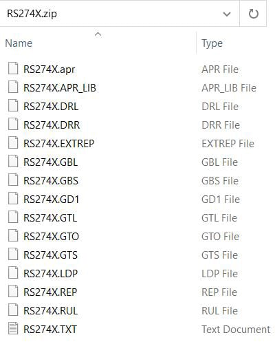
Example of a complete electronic data set in RS274X format, completed with drill, copper layers, mask, legends and a fabrication drawing.
A solder mask for each side is needed and a silkscreen legend for the top or both sides is usually provided. The mask should be universally sized and noted if special handling is needed. The legend should be legible, encroached or covering solder areas will need to be taken care of prior to production.
The last file, but certainly not the least, is an IPC netlist. This is always a great idea to have with the data set it is the only way to verify there are no known issues with the file set. Today, not many customers provide this critical piece to the puzzle we are going to build.
Fabrication drawings containing print notes, drill maps, hole charts, and dimensions are critical and prevent delays. Providing hole and mechanical tolerances is helpful for engineering. It should contain specifics about the PCB such as, the finished copper weights expected, surface finish, the colors of the mask and legend, a stack up showing any critical dielectric thicknesses, the overall expected thickness including the tolerance to be met. The classification to be met includes Class II, Class III, mil-spec, ITAR, or any customer specification needed.
Summary
When you think of PCBs, or any of our products for that matter, the data is the base of what we do. Complete or not, we can help you through the process and provide the resources to your success. Knowing what a complete data set is always the first step. Consult Epec engineering on our free DFM service to review your documentation today.
Key Takeaways
- PCB data formats have evolved significantly: From floppy disks and silver films in the past to Gerber RS274X and ODB++ today, data delivery has become faster, cleaner, and less error-prone.
- A complete data set is essential for accurate production: Standard files include NC Drill programs, copper layers, solder mask, silkscreen legends, board outline, and a fabrication drawing.
- Netlist files are critical for verification: Providing an IPC netlist helps detect file inconsistencies early, reducing risk of incorrect builds and delays.
- Fabrication drawings prevent miscommunication: Details like copper weights, surface finish, color, stack-up, tolerances, and classification standards ensure smooth manufacturing without unnecessary back-and-forth.
- DFM review is the first step to integrity: Epec’s engineering team uses design for manufacturability checks to validate data sets, catch errors, and confirm readiness before production.


