


For many narrow to wide bandwidth band pass applications, pure band pass filters (also bandpass filters or BPF) are a good fit, - forming rejection bands below and above the passband in a single filter. Coupled line, combline, and interdigital are three pure band pass filter types. Pure ilters can be the most efficient solutions for loss and physical footprint where the specs mandate their usage. For ultra-wideband applications, pure solutions may require too many poles making physical size too large and insertion loss too high for many systems.
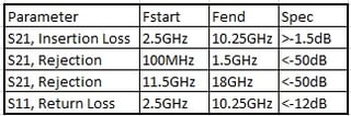
Additionally, the resonance of a band pass will be closer to the passband the broader the passband gets, limiting isolation bandwidth. For some topologies, very wide bandwidths are not even possible to achieve. For ultra-wideband applications, it is often necessary to split the band pass filter into separate high pass and low pass filters so that the upper and lower edges can be defined separately, and filter size and insertion loss can come down and resonances can be kept a reasonable distance outside of the upper band edge. For the purpose of experimentation, the following filter specification was created as a benchmark to design against.

Limitations of Edge Coupled Band pass
Four alternative pure band pass topologies are shown in Figure 1, an edge coupled resonator topology, a hairpin topology (essentially edge coupled resonator rearranged for real estate), a tapped interdigital topology, and a tapped combline topology.

Figure 1: Alternative Pure Bandpass Topologies
First, an edge coupled BPF with the same number of total poles as the HP/LP solution, below, was modeled. The results in Figure 2 show the broadest bandwidth possible for the topology, about 67%, while the goal spec for this experiment is 112%.

Figure 2: Broadest Bandwidth Possible for Edge Coupled BPF
This eliminates this topology as a potential solution. Figure 3 shows the response of a tapped interdigital topology. This topology can meet the bandwidth but resonates immediately. Since the goal spec is -50dB rejection out to 18GHz, this topology will not be useful for the solution without adding a series cleanup lowpass filter to it, growing the package size and insertion loss of the device.

Figure 3: Response of a Tapped Interdigital Topology
Figure 4 shows a tapped combline approach to the solution. This approach results in a very narrow band filter again, making it impossible to use this topology for the solution. The maximum bandwidth in this topology is 3.9GHz, or 62%.

Figure 4: Tapped Combine Approach
Separate High pass and Low pass Design
High Pass
The high pass edge was designed to meet 1.5dB insertion loss above 2.5GHz and 50dB of isolation below 1.5GHz, with no re-entry mode below 18GHz. A suspended substrate topology was used for lower loss in the mostly air dielectric and large series capacitors using coupling between the two layers on the suspended core. It is a 4 Pole filter and is plotted in Figure 5.

Figure 5: our Pole Filter
Low Pass
The low pass edge was designed to meet 1.5dB of insertion loss below 10.25GHz and to have rejection of 50dB above 11.5GHz, with rejection extending out to 18dB. The low pass uses open stub resonators, which are chosen for more tunability. It will be printed on the same PCB core as the high pass filter, although it only uses one layer. The modeled response is shown in Figure 6.

Figure 6: Low Pass Filter Modeled Response
Combined Band Pass
The low pass and high pass sections above were simply stitched together in series to create the 112% bandwidth band pass filter from the goal. Minimum tuning at the junction was the only change. The resulting filter response in Figure 7 very nearly meets spec across the goal and likely would meet spec with some minimum VSWR tuning.

Figure 7: Broadband High Pass/Low Pass Series Bandpass

Summary
Combining low pass and high pass filters in series is one way to get very broad bandwidth on a band pass filter while maintaining broad rejection bandwidth. The full specification should be weighed against the various available band pass topologies to determine which to use. If the spec is very broad band with broadband rejection as well, the high pass/low pass series band pass may be the best option. Combinations of these cascading high pass/low pass sections work very well in diplexers and multiplexers as well. Or, one could use a high pass filter with cutoff above the low pass filter, connect them in parallel with two T-junctions, and create a broadband notch. There are many potential applications for this topology.
Key Takeaways
- Pure bandpass filters face limitations at ultra-wide bandwidths: While coupled line, combline, and interdigital filters are efficient for narrower bands, they become impractical at very broad bandwidths due to excessive pole requirements, higher insertion loss, and large physical size.
- Series highpass/lowpass design provides a practical alternative: Splitting the passband into separate highpass and lowpass elements allows independent control of upper and lower cutoff frequencies, enabling much broader bandwidths and better rejection performance.
- Suspended substrate highpass designs improve performance: Using suspended substrate topologies reduces loss by leveraging mostly air dielectric and large coupling capacitors, making them well-suited for wideband highpass sections.
- Lowpass sections with open stub resonators add tunability: Open stub resonators provide flexibility in fine-tuning the lowpass response, which complements the highpass section when stitched together in a series bandpass design.
- Series HP/LP filters support complex broadband systems: Beyond standalone bandpass filters, this approach is effective for diplexers, multiplexers, and even broadband notch filters, offering engineers versatile solutions for wideband and high-rejection requirements.


