


Heat dissipation is the ability of a part, whether a circuit or any other component, to take the heat that's being generated by a component or an element of the design and to distribute it, dissipate it, and make the heat go away, for lack of a better phrase. This prevents the temperature of the part from continuing to elevate as the device is operated.
In this post, we will review the key factors to be aware of when designing a flexible circuit board that requires heat dissipation.
Heat Dissipation in “Some” Flex Circuits Designs
We see a number of flex circuit designs that have either high-temperature components that generate a lot of heat or are required to carry a high level of current, which in and of itself, has the opportunity of creating heat.
If you don't manage that heat, you can run into some significant reliability problems. Heat dissipation is heat dissipation, no matter what the circuit is manufactured from. We see heat dissipation requirements in rigid circuit boards just as much as we see in flex circuits

Applications
The primary ones that we see are high-intensity LED lighting applications and power distribution within the final assembly which carry significantly higher levels of current. They're used to distribute power and ground as opposed to the low current level signals of the electronics.
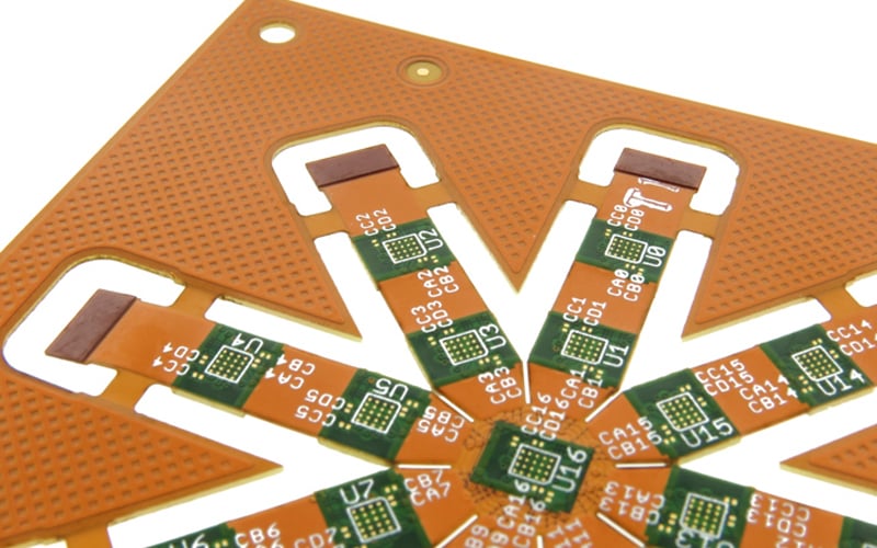
Multilayer flex circuit with solid copper planes for heat dissipation.
Consequences of Insufficient Heat Dissipation
If a flexible circuit board generates a significant amount of heat and that heat is not dissipated in some way, shape, or form, and is allowed to accumulate the resulting increase in temperature of the circuit and its components can create a number of issues. The components themselves may start to fail in their operation. LED lights are one of them. For those high-intensity LED lights, you need to manage that heat, otherwise, you can damage the LED itself. This also applies to active electronic components as well.
In applications where you have high power distribution, if that heat starts to increase, the resistance of the circuits also starts to increase. This in turn creates more heat and more resistance to the point where the circuits may turn into a fuse and potentially blow open like a circuit breaker creating open circuits and the circuit will stop functioning.
From a materials point of view, there is a concern that one of the components in a flexible circuit is a flexible adhesive which is used for multiple purposes. The most common purpose is to attach or laminate the external polyimide coverlays onto the surface of the circuitry. The coverlays serve the same purpose as solder mask on a rigid board, and that is to insulate the circuitry from the surrounding environment and encapsulate it. Flexible adhesive is also used in multi-layer circuit designs (3 layers or more) where there will be one or more layers of adhesive internally laminating the layers together.
Of all the components in a flex circuit, polyimide, copper, and flexible adhesive, the adhesive has by far the lowest continuous operating temperature range. It's significantly lower than polyimide, which is in the 400 degrees Celsius range. The adhesives that we generally use are flexible epoxy-based, which have a maximum operating temperature of approx. 140 degrees Celsius. If a flexible circuit is allowed to operate and exceeds the maximum continuous operating temperature of the adhesive, it will start to break down and potentially release. This creates a potential worst-case scenario of the flex layers delaminating from each other and the circuit potentially coming apart.
A higher temperature-rated polyimide-based adhesive is available which can withstand up to 220 C, however it requires a very high-temperature lamination process, which is much higher than what is used in normal flexible circuit manufacturing. Not all manufacturers will have the specialized high-temp. lamination equipment to work with polyimide adhesive. In addition, it’s significantly more expensive. There is also an acrylic-based adhesive commonly used in the industry. This adhesive is only rated at a much lower 80-90 C.
Flex Circuits Are Well Suited For Dissipating Heat
Flex circuits have a few advantages over rigid boards. The first, and they all combine together, so you don't take each one of these as a singular entity, is that polyimide itself is more thermally conductive than FR4. The ability of a material to conduct heat is also directly proportional to the thickness of the material. A thicker core will be more resistant to transferring heat.
Flex circuits use very thin cores in relation to FR4 rigid circuit boards. A 2-layer FR4 rigid circuit board standard thickness is 0.062”. A flexible circuit is substantially thinner in the 0.005” to 0.008” range. Due to its thinner construction, it will dissipate heat into the environment more efficiently than FR4. The combination of these two elements results in a much-improved surface-to-volume ratio. The total volume of a flex circuit is substantially less than the rigid board but retains the same surface area. That results in the inherent capability of a flex circuit to dissipate heat into the environment more effectively than you would with a rigid board.
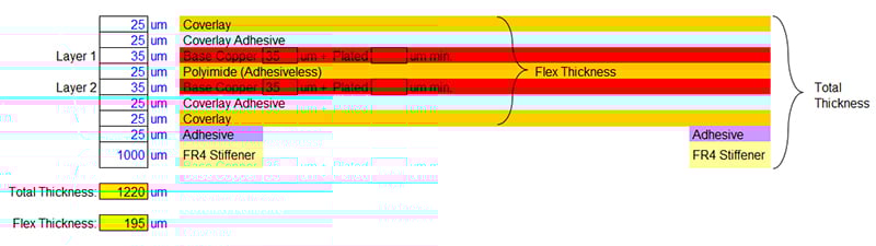
Standard 2-layer flex circuit construction.
Additional Heat Dissipation Options Available in Flex PCB Designs
Flexible circuits also have additional heat dissipation options available. Aluminum heat sinks are easily laminated to flex circuits to dissipate heat. Aluminum is preferred over stainless steel as it conducts heat much more efficiently. Localized selective copper planes can be added on either external or internal layers without resulting in an overly thick design. Copper planes are very efficient at distributing heat throughout a flex circuit and then having that heat dissipate out through the flex materials. Lastly there are thermally conductive Pressure Sensitive Adhesives (PSA) available that can be attached to a flex circuit and in turn used to attach the circuit to the metal enclosure of the final assembly. This allows the enclosure to be utilized as a heat sink. The use of PSA in not practical in rigid PCB designs.
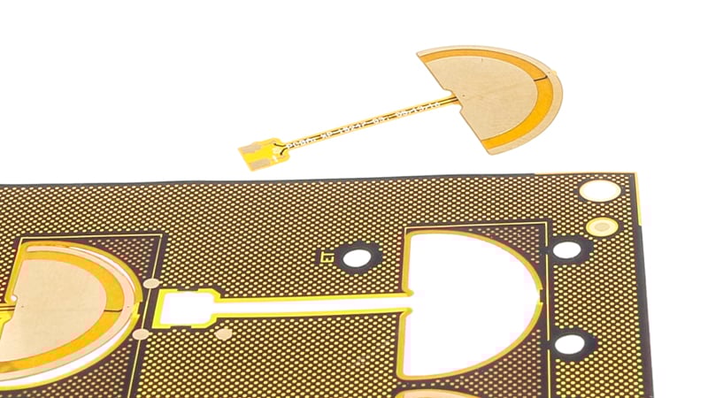
Flex Circuit with PSA attached.
Summary
To effectively dissipate the heat generated in a flexible circuit board there are several strategies that can be applied. The size and shape of the flex circuit can be adjusted to increase its surface area and in turn its surface to volume ratio. Thinner ½ mil core and coverlay materials are available to further improve the surface to volume ratio of the design and its heat dissipation capability.
Heat sinks can be easily added as well as internal or external copper planes. And thermally conductive PSAs can be used. The end result is a number of strategies that can be applied in a flex circuit design to manage heat that is either not available or not easily applied in a rigid circuit board.
Key Takeaways
- Heat Dissipation Defined: Heat dissipation prevents components from overheating by distributing and managing generated heat, ensuring the reliable operation of flexible circuit boards.
- Applications with High Heat Challenges: Flexible PCBs face heat dissipation challenges in applications like high-intensity LED lighting and power distribution, where elevated temperatures can affect performance and reliability.
- Consequences of Poor Heat Management: Insufficient heat dissipation can damage components, increase circuit resistance, and degrade adhesives, leading to delamination, open circuits, or complete failure of the flexible PCB.
- Flex Circuits’ Heat Dissipation Advantage: Compared to rigid boards, flex circuits naturally dissipate heat more efficiently due to thinner cores, improved surface-to-volume ratios, and the thermally conductive properties of polyimide.
- Additional Heat Dissipation Strategies: Design enhancements such as aluminum heat sinks, copper planes, and thermally conductive pressure-sensitive adhesives (PSAs) further improve heat management in flexible circuit designs.
- Material Considerations: Flexible adhesives typically have lower temperature tolerances than polyimide, making material selection critical for high-heat applications. High-temperature polyimide adhesives are available but costly and require specialized equipment.
- Customization for Heat Management: Adjusting the size, shape, and material thickness of a flex circuit, along with adding heat-dissipating components, provides tailored solutions to handle specific thermal requirements.
- Flex Circuits Outperform Rigid Boards in Heat Dissipation: Strategies like PSA usage and selective copper planes offer heat dissipation options in flexible PCBs that are impractical or unavailable in rigid designs.


