


Many flexible circuit board applications require designs to be exposed to and or operate continuously at elevated temperatures well beyond that of standard room temperature. These requirements are above and beyond the requirements of component or connector assembly.
Materials for flexible circuit boards are rated to withstand a RoHS solder reflow temp profile. These applications vary from short-term elevated temperature exposures, such as autoclaving of medical devices, to designs that operate continuously at extreme temperatures, such as down hole drilling electronics and applications that can see greater than 200°C for extended lengths of times.
To address these requirements, the industry has a variety of flex materials that have different maximum operating temperature capabilities. The end result is a dependable flexible PCB design that will be built on the materials specified throughout the construction.
In this blog post, we will review the properties of the available flexible PCB materials and resulting flex circuit constructions that will meet your operating temperature requirements.

Flexible Circuit Board Material & Construction Overview
Flexible circuit boards are constructed of 3 standard materials: copper for the printed circuit board patterns, flex core(s) to which the copper circuitry is attached, and coverlays, which encapsulate the external circuit layers serving the same function as soldermask on a rigid-flex printed circuit board.
Some flex circuit designs may also require stiffeners, to support component/connector areas, PSAs (double-sided, pressure-sensitive adhesive) to attach the flex within the enclosure or shielding films for EMI-sensitive applications. For each of the above materials, there are multiple options that have different maximum operating temperature capabilities. For a typical -40°C to 85°C requirement, all standard flex materials are capable, and no additional material or construction-related considerations are necessary. At higher temperatures, the materials and constructions will need to change.
Flex cores are available in two different types of constructions. They differ in how the copper circuit layer(s) are attached to the central polyimide core. The original flex core materials use a layer of adhesive to bond the copper to the polyimide core. The later material type has the Polyimide cast directly onto the copper thus eliminating all adhesive layers. This type of flex core is referred to as an “Adhesiveless Flex Core”. The standard practice, once the temp requirements rise above the common 85°C requirement, is to use adhesiveless flex cores. We will discuss the specifics as to why further along in this blog. The polyimide layer as a maximum temp in the 400°C range and is not of concern.
Coverlays consist of an external polyimide layer and a layer of flexible adhesive. They are laminated, under heat and pressure, onto the surface of the circuits with the adhesive serving both to attach the coverlay and to encapsulate the circuitry. There are 3 different types of adhesive available all with different temp rates which we will discuss in detail further along in this blog.
Stiffeners are available in polyimide, FR4, stainless steel, and aluminum. Stiffeners are attached using either the same adhesives as used with coverlays or in some cases a PSA. The only temperature-related considerations are if FR4 is used, and the type of adhesive used for attachment.
PSAs are available in an extremely wide range from multiple suppliers. 3M and TESA are the most commonly used material brands. The PSA selected will need review to ensure it meets both the temp and adhesion requirements of the design specification.
Flex circuits can be EMI shielded using either additional copper layers, dedicated shielding films, or silver ink layers. The use of silver ink has diminished significantly over the last 10 years and is not commonly recommended anymore.
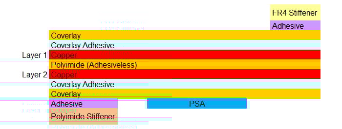
Example of a 2-layer flexible printed circuit board construction.
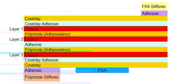
Example of a 3-layer flexible printed circuit board construction.
Flexible Adhesives
Flexible adhesives are used in three specific areas: coverlay attachment, layer-to-layer lamination in 3-layer or greater designs, and stiffener attachment. There are three types of adhesives that can be used: acrylic-based, modified flexible epoxy, and polyimide coating. Each of these have different continuous operation temperature ratings. Acrylic adhesives have the lowest temp rating and are used for standard applications without any significant elevated temperature requirements. Epoxy-based adhesives are rated in the 130 – 140°C range and polyimide base adhesives are rated at 220°C+. Epoxy adhesives, as an example, are suitable for medical applications that require autoclaving.
Polyimide-based adhesives, as an example, are required for down-hole drilling applications that have a 200°C continuous temp specification. Polyimide adhesives require very high temperatures for lamination. While acrylic and epoxy adhesives are laminated in the 180 – 200°C range, polyimide adhesives require 307- 316°C. Not all flex circuit manufacturers may have high-temp lamination capabilities. Polyimide-based adhesives are also significantly more expensive than acrylic or epoxy adhesives which are cost comparable.
We recommend that the adhesive requirements be specified in the fabrication drawing notes per IPCF specifications as follows:
- Acrylic Adhesive: IPC4203/18
- Epoxy Adhesive: IPC4203/19
- Polyimide Adhesive: IPC4203A/24
Flexible Circuit Board PSAs & Stiffeners
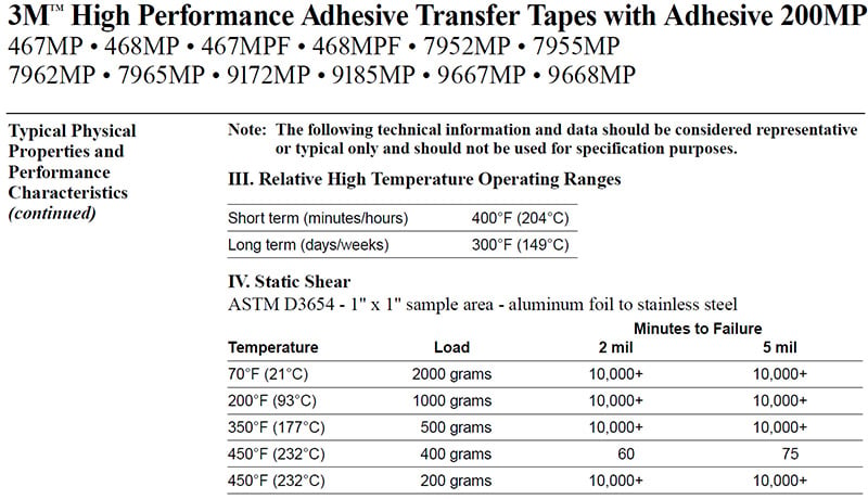
This an extremely wide variety of PSAs are available. Most have fairly high operating temperatures, but the adhesion strength will vary depending upon the temperature. For a flex application adhesion strength is usually not a significant requirement as the PSA on the flex is not subjected to any high forces. The following is the specifications for the most commonly used 3M 467MP PSA as an example:
For stiffener applications, beyond the previously discussed adhesive requirements, the only potential temperature issue may occur with FR4 stiffeners. Stainless steel, aluminum and Polyimide stiffeners have temperature ratings way beyond what will be required. We recommend following the same FR4 requirements for a comparable 2-layer rigid-flex PCB operating at the same temperature for the FR4 stiffeners.
Flex Circuit EMI Shielding
EMI shielding can be achieved using either EMI shielding films or additional solid, or cross-hatched, copper layers. We will not cover silver ink shielding as this method is rarely used in modern designs. Copper layer shields provide the highest possible operating temps and will be temp-rated based upon the adhesive used as this will require a flex construction of 3-layer or more.
Flex circuit with solid layer of copper EMI shielding.
The negative impacts of copper layer shielding are the significant increase in flex thickness, and the resulting reduction in flexibility and bend capability, and the increase in part cost. EMI shielding films are the preferred solution for flexibility/bend capability and cost-effectiveness but is limited to 125°C max. continuous operating temp.
EMI shielding films are laminated to the surface of the part in a similar method as coverlays. The adhesive used in the shielding film is used to both attach the film and electrically connect it to the ground net within the flex circuit. Exceeding the operating temperature will increase the electrical contact resistance and potentially compromise the effectiveness of the shield. For temperatures greater than 125°C the only viable option is additional copper shielding layers.
Summary
We hope this blog has answered many of the questions that may arise when developing a high operating temperature flex circuit board design. Feel free to contact Epec if you have any questions. We look forward to the opportunity to discuss your specifications and review your design to ensure that it will meet your operating temperature requirements.
Key Takeaways
- Adhesiveless flex cores are essential for high-temp designs: Standard adhesive-based cores can break down at elevated temperatures, while adhesiveless polyimide cores withstand up to 400°C, making them the preferred option above 85°C.
- Adhesive type determines thermal capability: Acrylic adhesives are suitable for standard use, epoxy adhesives perform up to 140°C, and polyimide adhesives handle continuous operation above 200°C, such as in down-hole drilling applications.
- Stiffener selection impacts performance: Polyimide, stainless steel, and aluminum stiffeners all tolerate high temperatures, but FR4 requires additional consideration to ensure stability at elevated operating ranges.
- EMI shielding options vary by temperature: Shielding films are cost-effective and flexible but limited to 125°C, while copper shielding layers withstand higher operating temperatures at the expense of thickness, flexibility, and cost.
- Material choices must match application environment: From adhesives to PSAs and shielding methods, every material must be specified for the required temperature range to ensure both electrical and mechanical reliability of the final design.


