


In the rigid printed circuit board (PCB) world, you can easily generate a quote with cookie cutter specs, such as 0.062” thick, with FR4, green soldermask, and white silkscreen. With those standard specifications, you could quote a huge number of rigid PCBs.
Now try to do that with flexible PCB or a rigid-flex design. The specifications may look something like, 0.005” thick, with coverlays, adhesive polyimide, stiffeners, PSAs, and white silkscreen. What we’ve seen in our experience is the provided specifications sent in by customers are not enough to provide an accurate quote. We want to help our customers succeed, and we want to build quality parts for them.
In this blog post, we will identify some of the variables that can affect pricing and delivery when manufacturing flex and rigid-flex circuit boards.

Flexible Circuit Boards are a Different Species
Flexible printed circuit boards often have stiffeners, which can be fabricated form polyimide, FR4, or stainless steel. They have coverlays or flexible soldermasks. They may be a flex-only design or a rigid-flex design. They might have flex sections that do not need to flex with rigid stiffeners underneath. You may also find flexible circuits that need to bend once or flex that needs to bend dynamically all the time over and over.
Rigid circuit boards are generally thicker than flexible circuit boards as they do not need to bend. Where a flex PCB may be only 0.007” finished thickness, many rigid boards are 0.062” thick built with FR4. Because flexible circuit boards are made of polyimide, which bends easily, stiffeners are many times required to aid in assembly. This extra step of processing should be included on the quote.
Coverlays are required to protect the signal circuitry. Coverlays are also made of polyimide. If tight SMTs are present in the design, flexible mask can be used selectively in place of coverlays, although it is less flexible.
When submitting a quote, you must also include whether the design is just a flex PCB or a rigid-flex design. A rigid-flex circuit board design is a combination rigid design, plus a flex area consisting of the thin polyimide areas.
Understanding the differences of these additional requirements of a flexible circuit is critical to not only getting an accurate quote, but it allows for a high-quality product to be manufactured without any issues during production.

Specifying Stiffeners in Your Design
When specifying stiffeners in your flexible circuit board design, there are a couple of items to remember. What stiffener material will be used and what is the thickness?
- Stiffener Material & Thickness:
- Standard FR4 = 0.010” – 0.059”
- Standard Polyimide = 0.002” – 0.008”
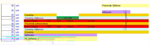
Example of a flexible PCB stack-up using polyimide stiffeners.
The example above shows polyimide stiffeners on the top and bottom layers. The top side has a combination coverlay and flexible soldermask, and also, adhesiveless polyimide core. By the way, all the copper weights are shown at half ounce. This is important because of the type of stiffeners being used. Plus, the addition of a flexible soldermask area shown in this design requires additional processing during the manufacturing of the parts.
Special Requirements
If your part requires any type of special requirement (see items below), these need to be identified during the quoting process. Some of these additional items can increase the cost of your part, the lead time, or both.
Pressure Sensitive Adhesive
Your flexible PCB design may require a pressure sensitive adhesive (PSA) or simply a double-sided tape for assembly mounting. We typically use 3M 467 for single boards and 3M 9077 for boards in arrays because it can handle higher temperatures for assembly.
These special requirements are not just items listed on a quote, but require additional processes, as the PSA is manually added during the production of these parts.
Stiffeners
Polyimide stiffeners are also manually added during the production process. Every time a manual process is required during the production processes, more time is required, and this can increase the cost and lead time.
Shielding
In some cases where the flexible circuit requires shielding, there are silver ink shields (or shield films) applied on the circuit boards. This process is used to lower radio frequency (RF) electromagnetic (EM) interference in the design. This interference can be detrimental to a design's reliability, even to the point of an assembly becoming nonfunctional.
Controlled Impedance
Controlled impedance is a critical feature of many designs. Trace pairs must have consistent width and spacing to each other to have the correct resistance measured in ohms. In flexible circuit boards, just as in rigid circuit boards, controlled impedance traces must refer to ground planes. A flex PCB also needs an extra layer of polyimide core added in between an impedance layer and its corresponding reference plane layer. Basically, this means we need 2 sheets of polyimide instead of 1. This not only adds to the cost, but it is a necessary part of these kinds of builds.
Non-Standard Plating
With flex, we do have standard pattern plating where the entire artwork image gets plating plus in the holes. But, we have quite a few designs that get pad plating. That is selective plating that only plates the SMT areas and very little in the holes. Pad plating is very good for controlled impedance boards or boards that need to be very flexible.
Surface Finishes
Common board surface finishes for flexible PCBs include HASL, ENIG, gold, and immersion silver. The best finish for flexible circuit boards currently is ENIG. It is a thinner, more flexible finish for assembly. Gold finish is OK as well, but usually should be specified as gold flash, because it is thinner. It is more flexible than a full hard gold plate, which would not be flexible.
Flex & Rigid-Flex PCB Stack-Ups
Flex and rigid-flex PCBs have a wide variety of stack-ups that can be used. The stack-up build of the boards also affects the quoting.
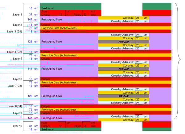
Below is an example of 10-layer rigid-flex printed circuit board. As you can see, there is soldermask for the rigid areas. The soldermask does not have to be flexible mask. Then there are coverlays for the internal flexible layers. A lot of adhesive is shown as well as this is needed to bond the build together. Generally, prepreg is the adhesive for rigid multilayers, and adhesives bond the flex portions.
Example of flexible circuit boards in a modified array with rolled annealed copper.
Below is an example of a 3-layer rigid-flex stack-up. This has soldermask on top, and coverlay on the bottom portion. That is because the bottom two layers need to be flexible. Imagine all the combinations that could be used for flex and rigid-flex stack-ups, then you can see how when we have enough information, we can provide an accurate quote.
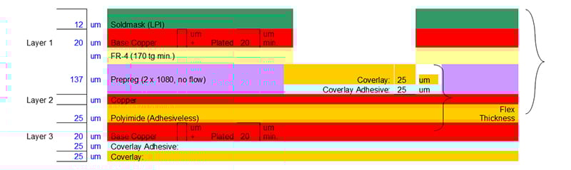
Example of a 3-layer rigid-flex PCB stack-up.
Array Specifications for Flexible PCBs
Assembly arrays are often used for component assembly manufacturers in order to save time and money as opposed to manually assembling PCBs. There are more rules when setting up arrays for flexible circuit boards than there are for rigid circuit boards.
One-layer and 2-layer flexible circuit board arrays need to fit within a 9-inch-wide dimension due to the width of the polyimide material rolls. As shown below, the orientation of these arrays changes if the copper is to be rolled annealed (RA) copper. The orientation of the stiffeners also comes in to play based on what type of stiffeners they are.
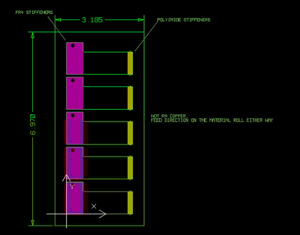
Example of flexible circuit boards in an array with stiffeners using standard copper.
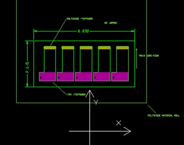
Example of flexible circuit boards in a modified array with rolled annealed copper.
Multilayer flex and rigid-flex PCB arrays need to fit within a 12x16” production panel area. The number up in an array is a factor of the design being tight lines and spaces or not, as well as how flexible the boards are. It is not a good idea for flexible PCB arrays to be large like they can be with rigid boards.

Summary
It is important to understand these variables going forward when submitting a quote for your design. Providing this information up front will ensure that you receive an accurate quote and delivery times for the parts. Working with our engineering team on some off these special requirements ahead of time also helps us to provide you with an accurate quote the first time, but more importantly allows us to manufacture a highly reliable flexible circuit board.
Key Takeaways:
- Detailed Specifications Are Essential for Accurate Quotes:
- Flexible and rigid-flex PCBs require specific details like stiffeners, coverlays, adhesives, and special features to ensure accurate pricing and delivery estimates.
- Flexible PCBs have unique requirements compared to rigid boards due to their material composition and intended flexibility.
- Stiffener Material and Thickness:
- Common stiffener materials include FR4 (0.010” - 0.059”) and polyimide (0.002” -0.008”).
- Stiffeners provide necessary support for assembly and should be clearly specified in the design.
- Special Requirements Impact Cost and Lead Time:
- Features like Pressure Sensitive Adhesives (PSA), shielding (e.g., silver ink), controlled impedance, and non-standard plating require additional processing, affecting cost and delivery times.
- Controlled Impedance for High-Speed Designs:
- Trace pairs must maintain consistent width and spacing to achieve the correct impedance, requiring extra polyimide layers and precise design specifications.
- Controlled impedance is critical for ensuring signal integrity in high-performance applications.
- Surface Finishes for Flexible PCBs:
- Popular finishes include HASL, ENIG, immersion silver, and gold flash. ENIG is preferred for flexibility and assembly compatibility.
- Impact of Stack-ups on Quotes:
- Stack-ups vary widely for flex and rigid-flex PCBs, affecting material selection, adhesive use, and overall build complexity.
- Example stack-ups include 10-layer rigid-flex designs with solder masks and coverlays, or 3-layer flex designs for lighter applications.
- Array Specifications for Flexible PCBs:
- Arrays must consider the width of polyimide rolls (e.g., 9-inch max for 1–2 layers) and copper orientation.
- Larger arrays, common for rigid boards, are not ideal for flex designs due to their inherent flexibility and material constraints.
- Understanding Shielding Needs:
- EMI shielding, using silver ink or shield films, is essential for designs exposed to RF or electromagnetic interference.
- Collaboration with Engineering:
- Early engagement with engineering teams helps address special requirements and ensures manufacturability, improving reliability and accuracy in quotes.
- Summary of Best Practices:
- Providing comprehensive design details (e.g., stiffener material, plating type, surface finish) ensures accurate quotes and avoids delays.
- Detailed upfront planning minimizes production issues and leads to a higher-quality final product.


