


Rigid-flex printed circuit boards (PCBs) are a great solution to combine the benefits of both rigid and flex PCBs, but as a result, can accumulate the design challenges of both types alongside creating their own challenges along the way.
Moreover, careful considerations must be taken during the design phase to ensure the design is feasible in manufacturability while still achieving the primary function of the board. Challenges can range from determining impedance requirements and maintaining the values throughout the stack-up to accomplish them, preserving bend requirements, and managing trace routing and component placement without drastically increasing PCB size.
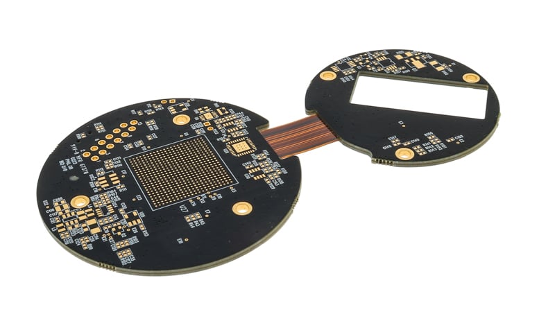
Example of a rigid-flex PCB design.
Maintaining Impedance Requirements
In a normal, rigid or flex PCB, impedance requirements can already be challenging. The traces must fall under and/or above ground planes to achieve a reference to the plane with a determined spacing or thickness to the traces. Many factors end up influencing the impedance, ranging from dielectric thicknesses and properties to copper thicknesses to line properties.

But with a rigid-flex PCB design, impedances can cross a variety of stack-ups from a rigid stack-up in one section to a flex section in another and back to a rigid section once more. Modeling this impedance can be time-consuming and difficult, having to balance each section individually to achieve a consistent impedance throughout the design or else risk losing crucial timings along the way.
The best way to achieve impedance like this is to vary the properties of the traces and balance the stack-ups to make up the difference. This could result in a trace thickness changing from one section to another, tapering down, or widening as needed to ensure a proper impedance. With a variable trace width, the stack-up can be easily changed and manipulated as needed.
Preserving Bend Requirements
The bend radius ends up being one of the most critical parts of a rigid-flex design. If a rigid-flex circuit board cannot bend to its requirements, or worse, if it cannot bend, then it holds little difference from a rigid board. Knowing the limits of the bend radius can be one of the most critical design elements to consider from the beginning, along with knowing the final purpose of the bends of the board, whether they be one-time installation bends or dynamic bend cycles through the lifetime of the part.
In essence, the bending capabilities of a rigid-flex PCB design differ very little from that of a flexible circuit design, following IPC 2223 guidelines for static and dynamic bend applications. The bend capabilities operate on the flexible section’s thickness, the number of bends necessary, the length of the flex section, and in special cases, the existence of plated thru holes (PTHs) in the flexible section or special shapes that are needed for flexible sections.
The best way to accomplish bend requirements is not always the same for all parts. Sometimes, the length of flex sections must be increased, sometimes the stack up needs to be minimized and thinned out, or sometimes a special epoxy mix known as strain relief must be applied at the transition edges to ensure the boards can bend without kinking. It is advised to always err on the side of caution, making the flexible sections as thin as can be allowed or giving wide lengths if an extreme bend is needed. The best solution may be to consult Epec directly, as we can get you in touch with our staff who can help advise on any design constraints you may have while still maintaining a manufacturable part.
Trace Routing and Component Placement
Designing a rigid-flex PCB also comes with a unique design constraint that directly correlates to its benefit. A benefit of a rigid-flex involves no longer needing connectors, instead relying on the flexible section to serve as a form of connector across the PCB. While this is useful in reducing part cost, it can hamper a design by reducing usable space for assembly. Portions of a board that could be usable in a rigid board, such as space within the 0.050” space to a rigid-flex transition, no longer become usable due to IPC-2221 design guidelines stating no vias within 0.040” to 0.050” of a transition.
Another design constraint also relates to the benefit. Due to the flexing of the design, components must be placed carefully to ensure they do not collide with the board in flexing. With that in mind, component placement must be considered from the very beginning, working in tandem with the bend and twist considerations of the rigid-flex PCB and the final mounting of the PCB.
In addition, traces must be placed far more carefully than a normal PCB. Traces must be routed with consideration of component locations, spacing requirements, and heat management, if applicable to this design. This means that every trace must be placed with care and consideration to everything throughout the design without interfering with via holes, impedance requirements, or any other design requirements.
Summary
Rigid-flex PCBs can be one of the most powerful solutions when designing. With this great power comes more avenues to manage the design, ranging from impedance requirements to bend requirements to trace routing. Due to this, a rigid-flex PCB can be significantly more difficult to design than a flex or rigid PCB. If done properly, however, it can save costs by removing the need for connectors and consolidating multiple PCB needs into one singular PCB.
Here at Epec, we can help advise on the design of flexible and rigid-flex needs for many applications. Please feel free to contact us to discuss the details of flexible or rigid-flex designs and any concerns that you may have.
Key Takeaways
- Impedance consistency is complex: Rigid-flex boards require careful modeling to maintain controlled impedance across different stack-ups, sometimes needing variable trace widths or spacing to balance signal performance.
- Bend radius must be prioritized: The flexibility of the design depends heavily on thickness, length, and bend type; exceeding IPC 2223 guidelines can lead to failures, so keeping flex sections thin and properly supported is critical.
- Trace routing requires precision: Because rigid-flex eliminates connectors, routing must account for mechanical constraints, spacing rules, and thermal considerations without compromising performance.
- Component placement is more restrictive: Designers must avoid placing components near transitions or in flexing areas to prevent mechanical interference and damage during bending.
- Early design reviews reduce risk: Working closely with an experienced fabricator during layout ensures manufacturability, minimizes redesigns, and helps balance cost, function, and reliability.


