


When our customers are in the preliminary stages of launching a new SMART HMI project, they typically reach out seeking advice on the best way to start. With what can amount to a near infinite number of HMI design options and system feature combinations, brainstorming an embedded firmware project can quickly become overwhelming. Where does one begin? How does the firmware work? What level of detail is required now?
User Interface Front Panel
Importance of a Requirements Matrix
The most important lesson when dealing with firmware and software development is summed up by the saying “garbage in – garbage out”. What this means is that we, Epec, are not experts in our customers product or application. We are experts at interpreting clients' requirements and creating an executable project plan while educating on the pros, cons, risks, opportunities, and many other design options that can help solve our customers' design goals. This creates a critical need for our customers to formulate a requirements matrix of the system that includes the multitude of “must have” and “nice to have” design features in order to begin to manage costs. It is vital to gather as much detail as possible to be able to deliver the custom SMART HMI that our customer needs.

What Should the SMART HMI Do?
Going hand in hand with the requirements matrix creation is the goal to completely capture what the SMART HMI should do. Some products may purely function as a switch, where they interpret 9 switch actuations and send those “ON/CLOSE” switch statuses elsewhere. A robust firmware solution can do much more by creating locally interpreted and executed commands such as turning on the backlighting of a display when a switch is held down for 5 seconds or more. More complex examples include functions like triggering an alarm and flashing a warning message if a sensed temperature exceeds 100 degrees or even diagnosing failures in a pump and prompting error messages. Firmware can truly execute a near infinite number of actions as long as there is sufficient power, hardware, and the robust code to drive it.
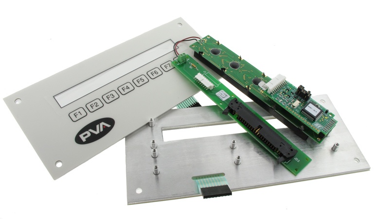
Firmware Considerations for the HMI Display
HMI displays range in complexity from simple discrete illuminated LEDs, to segmented alphanumeric LEDs, all the way to monochrome LCD screens and colorized touchscreens. The type of display can drive component selection, board layout, power, and I/O connections. Firmware can be impacted just as much so it is important to specify early on the type of display as this will go hand in hand with how the source code is prepared.

LCD Paired with Ruggedized Front Panel
Firmware Changes Can Impact More Than Just the Code
One of the most common mistakes as the requirements matrix takes shape and prototypes are built is a failure to understand the relationship between the embedded firmware and the hardware necessary to run the device. A major scope change to the system's firmware can trigger a redesign to the device’s hardware or even its mechanical structure. For example, projects can quickly become derailed if there is insufficient real estate on the PCB to accommodate a new IC or, even worse, if there is not enough power to drive a new suite of board level components. Both scope changes can be a death sentence for any juvenile project.

LCD Driver Assembly
Lessons Learned
After reflecting on numerous successful projects and others that experienced challenges, listed below are lessons learned to summarize some of the basics of firmware development:
- Revision control of both the requirements matrix and firmware are necessary and critical. Maintaining a proper revision log of both can be even more important. Since design changes and scope creep are common during development, it is inevitable there will be features and functionality that can be misunderstood or omitted. We strongly recommend all revision changes be in writing and signed off by all parties.
- Spend ample time identifying the requirements in fine detail. All interfaces need to be identified and documented. The project should not proceed until all parties agree to these requirements. This cannot be overemphasized.
- When properly incorporated, a serial BUS Interface can drastically simplify an otherwise complex system and can reduce the number of I/Os. This would be analogous to designing a matrix array to reduce the number of pins required a membrane switch.
- Consider connectivity options (Bluetooth, Wi-Fi, USB harness) early on to ensure there is sufficient real estate and power to properly operate these functions. This includes both wired and wireless system connections.
- Safety critical interfaces must be identified and addressed. Machine damage and, more importantly, human life may need to be considered. This includes accounting for SELV (safety extra-low voltage) requirements as well as firmware code to execute a command that would shut off power during a hazardous event.
- The addition of a design verification step should be considered to ensure all the requirements are met. Typically, this should be an ongoing practice performed during firmware development by the code author. At the completion of the projection a design verification document should be completed that describes, in detail, how the firmware complies with the requirements matrix, item by item and requirement by requirement.
- A common, detrimental mistake in any firmware development project is moving too far forward with a requirement that is incapable of being tested or verified. To mitigate this, it is important to consult with a test engineer during the initial requirement identification stage and consider product testing and the testability features to the firmware.
- Designing oneself into a corner can be catastrophic for any new project, especially in terms of available memory for firmware and data logging storage. Plan for future firmware upgrades by leaving a minimum of 25% memory resources available for additional features and functionality.
- Eliminate sole source components and micro-controllers where possible - industry standard items are always safest. This includes risky support components that may carry obsolescence risk. Always perform an EOL (end of life) analysis on all components since parts obsolescence can be a show stopper and is very expensive to redesign. Many component manufacturers will provide planned obsolescence information upon request.
- Provide an easy firmware update interface. SMART HMIs should be designed so that the customer can update firmware or fix problems in the field. A USB access on the exterior of the housing can provide a quick means of uploading firmware from a USB flash drive. Inside the housing could be a USB or debug port that can provide the same firmware update access but without being a field serviceable feature.
- A careful assessment of the product service life should be considered to safeguard against lost tribal knowledge pertaining to the code. Quite often the original author is no longer available when it matters most. The developer should provide ample design documentation during firmware development to ensure efficient firmware maintenance for the future. As field released and BETA versions are stressed, maintaining proper revision control and notations within the documentation in a simple readme.txt file can save significant financial resources in the future.
- When writing firmware, the tools (aka compilers) used should be documented and archived. These tool vendors can also go “obsolete” in the future just like components. Archiving said tool set is important because if future firmware modifications are necessary, one should use the EXACT tool set that was used on the original, regardless of tool set version updates. There are instances where these new updated tool sets will break the firmware functionality (sometimes this occurs in a subtle manner). This can create the need for expensive regression testing.
Summary
On the surface, some of the easiest firmware development projects are those that start with a clean sheet of paper where there are no requirements and the sky is the limit in terms of functionality. However, these loose requirement projects can churn along for weeks with no measurable progress and constant schedule slides to the right as the parties try to hone in on what they truly want. If you find yourself in a situation like this, there are three major activities to get the project back on track.
Complete the Epec HMI User Interface Request for Quote Form
This can help summarize your requirements and trigger ideas of what the HMI should look like and how it should act.
Create a Comprehensive List of “Must Have” and “Nice to Have” Features
This list can change daily, and one would likely receive different lists of “must have” and “nice to have” functionality depending on the disciplines of the parties asked. For example, the marketing department’s primary concern could be color matching, logo placement, or the ability to run off battery power for 12 hours. Conversely, engineers primary concerns could be the ability to survive a drop from 6 feet or pass a 15kV ESD discharge.
Component Specification Sequence
While this has an indirect bearing on firmware, the components and mechanical design can significantly impact how the firmware is written. If one decides they need a 7-inch touch screen after IC is sourced, this can create a major rework expense to accommodate the change in scope. For this reason, we recommend specifying the major (size or cost) components first as they are sometime the most difficult to change.
The following components should be carefully considered:
- Screen technology (touchscreen, LCD display, alphanumeric display)
- Power source (battery, transformer, power supply)
- Chassis/housing
- I/O connections
- Heatsinks/cooling fans
- Large SMT components (capacitors, ICs, processors)
- PCB and layer count
- Cable harnesses
- Ingress protection measures (gaskets/seals)
Key Takeaways
- Start with a detailed requirements matrix: Clearly define all “must have” and “nice to have” features to guide development, reduce scope creep, and avoid miscommunication.
- Understand firmware/hardware interdependence: Firmware changes can require significant hardware or mechanical redesigns, making early alignment essential to avoid costly project derailments.
- Plan for connectivity and expandability: Consider serial BUS interfaces, wireless/wired connections, and memory allocation early in design to ensure future flexibility and scalability.
- Prioritize reliability and longevity: Use industry-standard components, avoid sole-sourcing, plan for obsolescence, and document compilers, revisions, and tool sets to ensure long-term maintainability.
- Incorporate safety and serviceability: Identify critical safety interfaces, design for field firmware updates, and provide comprehensive documentation to support both immediate function and long-term support needs.


