


The prototyping phase presents one of the most challenging environments for flexible circuit board designs. During this stage, circuits are repeatedly installed and removed to validate form, fit, and function. This repeated handling increases the likelihood of mishandling, including excessive bending, dropping, or exceeding design limits.
In contrast, production environments follow controlled procedures where a trained technician installs the flex circuit once. Under these conditions, the same design typically performs with full reliability. As a result, many failures observed during prototyping are tied to handling rather than inherent design flaws.

ZIF Connector-Related Failures
Improper Insertion and Removal
Flexible circuits that interface with ZIF connectors are particularly vulnerable during prototyping. A common failure occurs when the connector latch is not fully opened before insertion. This forces the flex into the connector under pressure, increasing stress at critical transition points.
The highest risk area is where the coverlay ends and the exposed ENIG-plated contact fingers begin. The nickel layer within the ENIG finish is brittle, and bending in this region can lead to cracking. Once the nickel fractures, stress transfers to the underlying copper, which may also crack and create intermittent opens.

Example of ZIF contact area and crack formation area.
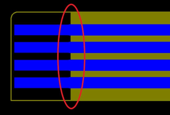
Example of flexible PCB ZIF connector area.
Damage During Extraction
Removing the flex without opening the latch can cause additional damage:
- Scratching of contact fingers
- Intermittent electrical contact
- Tearing of the flexible circuit
These issues are typically handling-related and are not indicative of production performance when proper procedures are followed.
Rigid-to-Flex Transition Risks
Stress Concentration at Transition Edges
The interface between rigid and flexible sections is a primary failure location due to differences in material construction. Sharp or repeated bending directly at the rigid edge can overstress the flexible materials, leading to cracked circuitry.
Attempting to rotate or pry the flex section, such as when separating a connector, can also initiate tears, particularly at transition corners. Although these areas are designed with a radius, this geometry provides only limited resistance to tearing under excessive force.

Example of a rigid-flex PCB stack-up illustrating rigid to flex transition areas.

Example of a rigid-flex circuit board, rigid to flex transition areas.

Example of a rigid-flex circuit board outlining transition corner radius.
Role of Epoxy Strain Relief
Some designs incorporate a flexible epoxy strain relief at the rigid-to-flex transition. This feature improves durability, especially in applications requiring tight bends near rigid sections. However, even with strain relief, improper handling or excessive force can still cause damage.

Example of a rigid-flex circuit board with epoxy strain relief.
Component Replacement and Rework Considerations
Replacing components on flexible circuits introduces additional risk, particularly at solder pad locations. Pads used for SMT and PTH components may lift or tear if subjected to excessive or repeated soldering temperatures.
This behavior is influenced by how the copper is bonded to the polyimide core, whether it is bonded with adhesive or cast directly onto the polyimide.
In both cases, overheating or repeated rework can weaken the bond between copper and substrate, resulting in pad detachment. Careful thermal control and minimizing repeated rework cycles are essential to maintaining circuit integrity.
.jpg?width=800&name=examples-of-assembled-flex-and-rigid-flex-pcbs%20(1).jpg)
Assembled flex and rigid-flex PCB examples.
Components located in rigid sections of a rigid-flex PCB design can generally tolerate similar handling and rework conditions as standard rigid constructions.
Folded and Creased Flexible Circuit Designs
Folding vs. Repeated Bending
Flexible circuits are often designed with folds to achieve compact shapes within an assembly. This approach allows the circuit to be manufactured flat, improving material efficiency and lowering cost. IPC 2223 design guidelines permit many 1- and 2-layer designs to be folded or creased, with an important limitation.
Folds are intended as a one-time operation. Once a fold is created, reopening and refolding the same area introduces significant risk.
Copper Ductility and Work Hardening
Creating a crease pushes the copper circuitry beyond its ductility, causing it to work harden and become brittle. While the circuit may remain functional after the initial fold, subsequent movement can cause cracking.
To prevent re-opening, many designs include a pressure-sensitive adhesive (PSA) in the fold region. This feature locks the fold in place during production. During prototyping, PSA may be omitted to allow fit evaluation, which increases the likelihood of temporary failures during this phase.
Reliability Testing and Design Qualification
Role of IPC 2223
The IPC 2223 standard defines design guidance for most flexible circuit applications. However, many designs incorporate unique geometries or use cases that extend beyond standard recommendations.
Prototype Testing and Iteration
For non-standard or highly complex designs, additional reliability testing is often required during prototyping. These tests help identify potential issues under real-world conditions.
It is common to produce multiple design variations within a single prototype build to evaluate different configurations. Because of the uncertainties introduced by new or unconventional features, some level of fallout during testing is expected.
Understanding Prototype Failures vs. Production Performance
Flexible circuit technology is inherently reliable and capable of solving complex mechanical design challenges. However, the repeated handling required during prototyping creates conditions that differ significantly from production environments.
Failures observed during prototyping should be carefully analyzed to determine whether they are caused by handling or by fundamental design limitations. In many cases, these issues do not translate to production performance.
Attempting to overengineer a design to prevent prototype-related damage is generally not practical and can introduce unnecessary cost without improving final product reliability.

Summary
Flexible circuit board technology is very reliable and solves many mechanical design challenges. The prototyping phase requires parts to be fitted many times over to finalize form, fit, and function. This excessive handling and potential inadvertent misuse can cause parts to fail.
These failures require review to ensure that they do not impact production parts, but in many cases are not a true indication of the effectiveness and reliability of the design. The option of overengineering a design to make it more reliable during prototyping is typically not practical and will add unnecessary cost to the design.
Key Takeaways
- Prototype handling introduces the highest risk of flexible circuit damage due to repeated installation and evaluation.
- ZIF connector misuse can lead to cracked ENIG finishes, damaged copper, and intermittent electrical issues.
- Rigid-to-flex transitions are sensitive to sharp bending, prying, and stress concentration at edge boundaries.
- Excessive soldering heat during rework can cause pad lifting or detachment from the polyimide substrate.
- Folded designs must not be repeatedly opened, as copper embrittlement leads to cracking.
- IPC 2223 provides design guidance, but unique applications often require additional validation and testing.


