



Flex circuits can be difficult to account for in many areas when designing, to such a large degree that it can be difficult to track every little thing. Some things can even drastically impact a design so much that they can cause fractures in copper, or even worse, delamination. The things that will most impact those failure mechanisms relate back to material selection, design choices, and assembly baking choices.
The challenge with flex and rigid-flex circuits is that many failures do not occur immediately. A design may pass initial electrical testing and appear perfectly functional, only to develop intermittent failures after installation, repeated movement, or exposure to temperature cycling in the field. Because of this, preventing fractures and delamination starts long before fabrication begins. It requires careful attention to materials, layout practices, and assembly procedures that work together to support the mechanical demands placed on the circuit throughout its life.

Material Selection Matters More Than Many Realize
Material selection is often one of the first opportunities to improve reliability, yet it is frequently overlooked until later in the design process. Flex and rigid-flex circuits combine multiple materials into a single construction, and each material responds differently to heat, moisture, and mechanical stress.
One important consideration is the coefficient of thermal expansion (CTE). Whenever a circuit experiences temperature changes, materials expand and contract. If the materials within a flex or rigid-flex design expand at significantly different rates, stress begins to build at the interfaces between them. Over time, this can lead to separation between layers, cracked adhesive bonds, or full delamination.
Selecting materials with similar CTE values helps ensure that the entire construction moves more uniformly during thermal cycling. This becomes especially important in applications exposed to frequent temperature swings, such as industrial equipment, aerospace systems, and outdoor electronics.
Adhesive selection is equally critical. A common guideline is to maintain approximately one mil of adhesive for every ounce of copper. While that may sound simple, ignoring this relationship can have significant consequences. If insufficient adhesive is used, coverlays may begin peeling away from the circuit during repeated bend cycles. What initially appears to be a minor cosmetic issue can quickly develop into a reliability concern.
Engineers should also carefully evaluate whether a design should utilize coverlay or soldermask in flexible regions. While soldermask performs well on rigid PCBs, it generally does not tolerate repeated flexing as effectively as coverlay. Excessive bending can cause soldermask to crack or separate from the surface, exposing conductors and creating opportunities for moisture ingress or mechanical damage.
Design Choices That Reduce Stress
Even the best materials can fail if the layout introduces unnecessary stress concentrations. Many fractures and delamination issues can be traced back to design decisions that seem insignificant early in development.
One effective technique is the use of hatched copper planes rather than solid copper pours in flexible regions. Hatched planes improve flexibility, allow moisture to escape more readily during processing, and reduce overall stress during bending. They also support tighter bend radii compared to solid copper areas.
Vias require special attention in flex and rigid-flex circuits. Whenever possible, vias should be kept out of flexible regions. A plated through hole is essentially a rigid copper cylinder embedded within a structure designed to bend. Repeated flexing can place significant stress on the plated barrel, leading to cracks and eventual electrical failure.
Similarly, vias should not be located directly beneath stiffener edges. The transition between a stiffened area and a flexible area naturally creates stress concentration points. Placing vias in these locations increases the likelihood of fractures developing over time.
Trace routing also influences reliability. Sharp corners, abrupt direction changes, and overlapping traces on multiple layers can create localized stress points. In multilayer constructions, overlapping copper can produce what is commonly referred to as the "I-beam effect," where stacked copper structures become significantly stiffer than the surrounding material. This stiffness can concentrate stress during bending and contribute to copper fatigue.
Repeated bending beyond the intended bend radius can further accelerate work hardening within the copper. As copper work hardens, it becomes less ductile and more prone to cracking. Designing for appropriate bend radii from the start helps prevent this failure mechanism.
Component placement is another area where caution is required. Components placed too close to bend regions transfer mechanical loads directly into solder joints and copper pads. Under extreme conditions, this stress can cause pads to separate from the substrate or initiate mechanical delamination within the circuit structure.
Assembly Practices Can Make or Break a Design
Even a well-designed flex circuit can be damaged during assembly if proper moisture management procedures are not followed.
The most important assembly consideration is pre-baking. Flexible and rigid-flex materials naturally absorb moisture from the environment. If that moisture remains trapped inside the circuit when the assembly enters a reflow oven, it can rapidly expand into steam.
The result can range from subtle internal separation to severe delamination throughout the circuit.
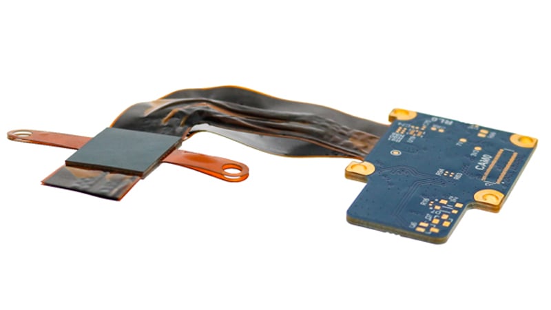
A rigid-flex PCB that has experienced catastrophic failure and delamination due to improper baking and assembly procedures.
Pre-baking removes absorbed moisture and helps protect the integrity of the construction during assembly. However, timing matters. The circuit boards should be baked immediately before assembly whenever possible. If they remain exposed to ambient conditions for an extended period after baking, moisture can be reabsorbed, and the process may need to be repeated.
Bake duration is also important. Higher layer count designs often require longer baking cycles because moisture has more pathways to penetrate and fewer pathways to escape. Engineers should consider both construction complexity and environmental exposure when establishing baking procedures.
Unfortunately, there is no simple repair for delamination once it occurs. Unlike many manufacturing defects, delamination is generally irreversible. In some cases, it may be barely visible. In others, it can spread throughout large portions of the assembly. Regardless of its appearance, once the layers begin separating, long-term reliability is compromised.
Summary
Flexible PCB designs can be difficult without running into fractures and delamination. Any time it is possible, both failure mechanisms should be considered from the outset to avoid remakes or redesigns. Typically, the cost of not accounting for those failure mechanisms can far exceed the cost of simply taking the time to ensure proper procedures and rules are followed.
The most successful flex and rigid-flex programs are rarely the result of a single design decision. Instead, they come from a combination of thoughtful material selection, proven layout practices, and disciplined assembly processes. By addressing potential failure mechanisms early, engineers can dramatically improve reliability and avoid costly surprises later in development or after the product reaches the field.
Key Takeaways
- Material compatibility is critical, especially when considering CTE values, adhesive systems, and the choice between coverlay and soldermask.
- Hatched copper planes can improve flexibility, reduce stress concentrations, and help minimize delamination risks.
- Vias should be avoided in flexible regions and near stiffener edges whenever possible to reduce the likelihood of copper fractures.
- Component placement, bend radius calculations, and trace routing practices all play a major role in preventing mechanical failures.
- Proper pre-baking immediately before assembly is one of the most effective ways to prevent moisture-related delamination during soldering and reflow processes.