


Selecting the optimum flex circuit board material is a key element to the success of a flexible circuit design. A wide variety of materials and configurations are available to address the needs of today’s design applications.
Material selection is determined by the combination of the electrical, mechanical bend requirements and cost considerations of a specific design. Electrical requirements, such as current carrying and impedance control, increase the flex thickness while high density designs require tighter bend capabilities of thin flex constructions. How the electrical and mechanical needs interact is a key element of the flex material decision making process.
Adhesive Based versus Adhesiveless Flex Cores
Flex core materials are available in two configurations, adhesive based and adhesiveless, that differ in the method used to attach the copper to the polyimide core. Adhesive based flex materials use a layer of adhesive, either acrylic or epoxy based, to glue the copper to the flex core. Adhesiveless flex materials have the polyimide cast directly onto the copper, eliminating the need for an adhesive layer.
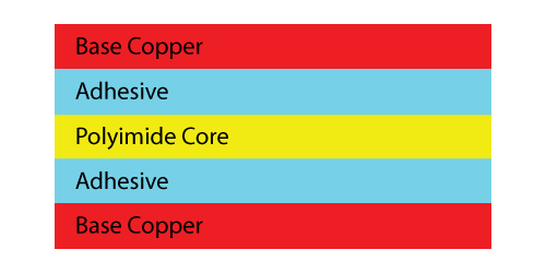 Example of an adhesive based flex core.
Some benefits of adhesive based flex cores include the reduction of material costs as well as a higher copper peel strength.
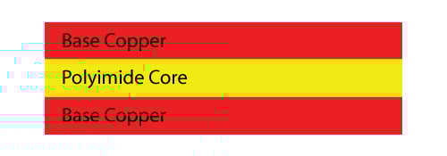
Example of an adhesiveless based flex core.
One of the major benefits of adhesiveless based flex cores is the elimination of the adhesive layers. Eliminating these layers reduces the overall thickness of the flex PCB which improves flexibility and minimum bend capabilities. This also Improves the plated through hole (PTH) reliability in flex circuit designs with a higher layer count. Additional benefits include improved controlled impedance signal characteristics and higher operating temperature ratings, which are better suited to harsh environment applications.

Both material types are available with a range of polyimide core thicknesses. The most commonly used are 0.001”and 0.002” which are the most cost effective. Adhesive based cores are inherent thicker than adhesiveless cores. Adhesive layers add 0.001” to 0.002” in thickness.
Thicker and thinner flex cores are available to meet unique specific design requirements. Thicker cores (greater than 0.002”) may be required for impedance controlled designs but have a negative impact on flexibility, bend reliability, and part cost. Thinner cores (less than 0.001”) are also available for designs that require maximum flexibility but negatively impacts cost.
Available Copper Thicknesses
There are a range of copper thicknesses available, but the most common and cost effective is ½ oz and 1 oz. There are thicker and thinner weights available based on the needs of your design, however these are more expensive and therefore less cost effective. For example, copper thicker than 1 oz is best used for higher current carrying requirements. Thinner copper, less than ½ oz, is utilized for high circuit density and highly flexible designs.
Copper thicknesses greater than 2 oz and less than 1/3 oz require specialized manufacturing methods. Using 2 oz or greater copper has a significant negative impact on bend capabilities requiring the design to be reviewed.
Copper Type: Electro Deposited and Rolled Annealed
Two types of copper are available in both flex material configurations: electro deposited (ED) and rolled annealed (RA). Both versions start as ED copper, but the rolled annealing process modifies the grain structure from the vertical of ED to the horizontal of RA copper.
ED copper is lower cost while RA is more ductile with improved bend capabilities. RA copper is required for dynamic flex applications.
Coverlay and Flexible Soldermask Materials
Flexible circuits have the external layer circuitry encapsulated with either a polyimide coverlay, a flexible soldermask, or a combination of both.
Coverlays consist of a solid layer of polyimide with a layer of adhesive, either acrylic or epoxy based, that is laminated to the surface of the part under heat and pressure. The adhesive also encapsulates the circuitry resulting in a percentage of the starting adhesive thickness being consumed. This results in the finished thickness of a flex circuit that will be slightly less than the sum of all the materials. Coverlays are the preferred material due to their improved flexibility and reliability over flexible soldermask.
Most common coverlay thicknesses are 0.001” or 0.0005” thick layer of polyimide. The adhesive thickness will vary from 0.0005” to 0.002” or greater depending upon the copper thickness to which it will be laminated against.
The common rule is a min. 0.001” of adhesive thickness is needed for each 1 oz of copper thickness. Excessive adhesive thickness is to be avoided as it will result in the adhesive be squeezed out from underneath the polyimide into SMT and PTH openings. This may create solderability issues.
Feature openings, for PTH or SMT pads, are created mechanically using either routing, laser cutting, or punch and dies sets. The minimum web thickness is limited to a minimum of approximately 0.015”. Less than this results in very fragile webs that are easily broken. This limits the size and spacing of openings, which requires multiple small openings to be ganged together into one larger opening.
Flexible soldermask is similar in capabilities to rigid PCB soldermask and is preferred for rigidized component areas with high density SMT components.
A common design practice is to utilize both materials within a design. Coverlay in flex areas and soldermask in component areas, as needed, to make best use of the capabilities of each material.
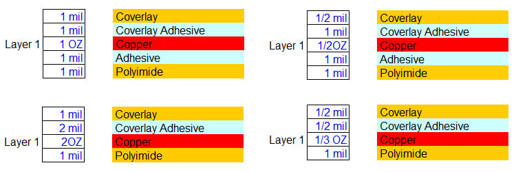
Example of common flexible Circuit board constructions.

Summary
There is a wide variety of flex circuit materials available, which allows today’s sophisticated designs to be achieved. Choosing the optimum configuration will depend upon combination of the electrical and mechanical specifications.
Key Takeaways
- Adhesive vs. Adhesiveless flex cores: Adhesive-based cores are lower cost and offer strong copper peel strength, while adhesiveless cores are thinner, improve flexibility, and perform better in harsh environments.
- Copper thickness impacts cost and bend reliability: Standard ½ oz and 1 oz copper are most cost effective. Thicker copper supports higher current but reduces flexibility, while thinner copper supports fine features and bending at higher cost.
- Copper type matters for bending: Electro-deposited (ED) copper is cheaper but less ductile, while rolled annealed (RA) copper is required for dynamic flex applications due to its superior bend reliability.
- Coverlay vs. flexible soldermask: Coverlay is preferred for flex areas due to better reliability and flexibility, while soldermask is often used in rigidized component areas with dense SMT layouts.
- Material trade-offs depend on electrical and mechanical needs: Balancing impedance control, bend radius, thermal performance, and cost is critical, and involving the PCB supplier early helps optimize material selection.


