


Among the most common questions printed circuit board suppliers receive are those dealing with production capabilities. Customers often suspect that they are about to design-in a feature which may be either at or outside their fabricator’s limits. Fearing that their non-standard feature may add cost to their product, they inquire to find out just how much pain they are about to cause.
In many cases the answer is that there is a straightforward way to do what’s needed without a lot of added cost. Other times, discussion reveals that the unusual requirement is either impossible, or nearly so. In these cases, additional work is necessary, so a compromise or workaround can be identified and implemented, allowing the order to go forward.
Too often, however, a circuit board design gets to the point where it is out for production bids before the customer discovers either that their project is going to be very costly, or that nobody is willing to manufacture it at all. This can become a panic situation, requiring a rushed redesign that sets back other work and leads to missed deadlines. The lost time can make it necessary to order prototypes on a rush basis, at premium pricing. Nobody ends up happy.
The best way to avoid such scenarios is to avoid incorporating features that are not production-friendly in the first place, but this isn’t possible without the benefit of a basic “feel” for where the limits of standard processing lie. Most fabricators have published standard design rules and preferences, but the reality is that these are not always maintained and kept up-to-date, so they may understate what is actually possible. Other suppliers attempt to be all things to all customers, so as not to frighten potential business away. In this post, I’ll attempt to lay out some strategies by which PCB designers can develop an understanding of standard PCB manufacturing process limits and preferences for the typical board supplier, so they can better sense when they are about to swerve outside of their lane.

The Starting Point: A Basic Understanding of PCB Production
Learning about the PCB manufacturing process is easier now than it was many years ago. In the old days, if one did not actually work in a board shop, resources were limited. Clyde Coombs, Jr.’s comprehensive Printed Circuit Handbook (updated several times since the 1960s, and still in print) was standard reading, along with Norman Einarson’s highly practical late-seventies textbook Printed Circuit Technology. Aside from those books, and a handful of industry-specific periodicals, not much else was available.
Today the Internet is an excellent source of information. It offers everything one could want - fabricator web sites, material supplier data sheets, video plant tours, and on and on. Ironically, though, the Internet’s strength - the availability of nearly limitless information - can be a designer’s downfall. Too much information, when read without context, can become a dangerous trap for somebody who does not understand how to interpret the information, or how to limit the scope of their search.
The result of too much Internet and not enough experience is that we frequently see inquiries for PCBs that call out mix-and-match requirements which are nearly impossible to meet in a real-world situation. For example, one quote request specified an exotic and costly base material that is popular in Europe but not in the USA or China, in combination with a conductive hole fill material from Japan, and a surface finish thickness that would have been impossible to achieve with the specified type. The customer, concerned that he was not receiving any bids, called us to ask us why we had been among those who had no-bid the work. We explained our reasons, assured him that other companies would have the same issues, and suggested substitutions. Eventually, after a complete redesign that conformed to the properties of the new base material, it was possible for us to produce some boards, but it should have been a lot easier than it was. The takeaway is that it’s not good policy to try to “roll your own” by relying solely on the Internet to guide you. So where should you look?
Filling in The Details: Self-Education
The best place to start depends on how much you already understand. If you have no idea at all about how PCBs are produced, then it’s not a bad idea to see whether it’s possible to arrange a tour of an actual facility. This may not be possible if there is not one within a reasonable distance, or if you cannot promise some potential for a sale somewhere not too far down the road. If, however, you are still a student or a recent graduate, sometimes it’s possible to get several people together from one or more area schools in order to arrange for a group tour. A plant manager may look favorably upon such a group as a pool of future customers, with the hope that they may remember the company that opened its doors to help them when they were full of more ideas than experiences.
In terms of gaining experience, there is nothing that will bring you up to speed more quickly than a tour through a plant. It is the one place where you can view the product at various stages of development, seeing, hearing, and smelling it as it moves from one station to the next. Any notion you may have had that the raw materials are slid into one end of a sparkling automated conveyorized unit to emerge at the other end as shiny new circuit boards will quickly leave you; you will see instead that a lot of the steps still involve a high degree of human oversight and interaction. Hopefully this will help you to understand why it is always best to design your products as close to standard as you can, whenever it’s possible to do so.
If you cannot find a plant nearby, or if they are not able to provide a tour, check out some of the video presentations available online. Although you will miss the sights and sounds of a live visit, it is sometimes a bit easier with video to follow what’s going on, and to grasp how one step leads to the next. In a physical building, it is not always possible to arrange departments so that they follow the production sequence. Instead, various departments are set up as space or infrastructure evolves; the trip that the product makes tends to zig-zag through the building in a less-than-100% rational sequence, making it difficult to tell what’s going on. A good promotional or educational video, on the other hand, will present the process using a start-to-finish sequence that demonstrates clearly how each step affects the next. It’s also possible while viewing on YouTube and some other platforms to use the viewer’s tools to slow down the footage for a more prolonged look. Importantly, too, you have the ability to view a video as many times as you can stand to watch it, whereas a busy plant manager will be obliged to escort your group to the exit after an hour or so.
Aside from plant tours and their video equivalent, familiarize yourself with the standards published by IPC, the industry standards organization. They publish comprehensive specifications, covering everything from design to final inspection. These specifications are not inexpensive, but if you are committed to a career designing PCBs, you owe it to yourself to eventually invest in at least a digital copy of design guide (2221 for rigid PCBs, 2223 for flex) and another for acceptability (6012 for rigid, 6013 for flex.) If you are already working for a company that designs PCBs, then most likely they belong to IPC and may have some or all of the specifications.
Besides IPC publications, the Coombs book is an excellent source for detailed information on materials and processing and is well worth the investment. There are other guides available, from hobbyists to specialists. These are listed below, as individual book reviews are beyond the scope of this post.
Design Rules and Understanding What Comes Standard
Having learned the basics of the production cycle, you now need to understand the rules of the game. If you’re using CAD software to generate your PCB files, you need to learn the design rules for the features you’ll use in your design, so you can produce clean, buildable files.
Most fabricators maintain published design rules on their company website. These cover rules for trace width, copper-to-copper spacing, minimum drillable hole diameter, maximum or preferred PCB outline size, etc. If you read a few of these, you will see that in most cases the values are very similar to one supplier to the next. You may also notice that many sites list multiple sets of rules, because process limits are driven by your design’s copper weight.
Many fabricators will further divide their capabilities into two categories. One will be for “standard” rules, while the other will be designated “special” or “advanced.” Whenever possible, use the standard set, and configure your CAD program so that your layout does not stray outside these rules except in cases where there is no other way to meet your design intent. Use of advanced values when they are not required is a big cost driver and can even render your board unbuildable.
Pay attention to materials and tools as well. Find out what material products your supplier stocks and use them or write your material specification to match the properties of the products they use. Special order material is extremely costly, especially for prototypes and small volume production.
Learn the standard rules for operations like solder mask application, plating thicknesses, PCB thickness, and mechanical tolerances. Whenever possible, simply default to IPC’s commercial standard (Class 2/Commercial). Doing so will save you time that would otherwise be wasted making redundant callouts. Any qualified participant in the manufacturing process understands what the IPC standards say and how to meet them, so calling out the spec is a form of shorthand upon which all of the participants can agree.
Understanding tools is important. Small drill bits can reduce the efficiency of the drilling cycle. They are brittle and prone to breakage and cannot drill as deep as larger bits. They force the fabricator to reduce the number of panels that can be stacked together which increases cycle time and adds cost. Small routing tools have the same problems. Below a .062” bit, routing can become another bottleneck as long cycles tie up machine time. Ask questions so that you can understand the points at which production becomes more difficult. Try to get a feel for times when you may be getting close to one or more limits and see what your fabricator can suggest. Often there is another approach which will work for your product and will improve the fabricator’s yield.

Understanding Some Potential Bottlenecks
Certain printed circuit board manufacturing steps lend themselves to becoming bottlenecks, where work is constantly stacking up and bogging down. There are several reasons why bottlenecks occur, and every shop is a little different. Some may lack sufficient capacity in certain areas, because of inadequate space, or inability to cost-justify having an extra machine on hand that will only run during peak periods. Others must outsource seldom-used processes on occasions when they are required. In general, though, certain processes lend themselves to bottlenecking even when there are strategies in place to counter them. The ability to counter these bottlenecks at the design stage is limited – sometimes you need the features you need, and little can be done to make them run faster. The key, then, is to not create needless bottlenecks elsewhere in the production cycle.
Drilling:
Drilling is an early bottleneck. With the prevalence of higher-density surface-mount designs, most holes on most designs are vias, and some via drilling cycles run into the tens of thousands of hits. Vias use those small, brittle, short-fluted drills mentioned earlier, meaning that drill cycles are less efficient because fewer panels can be drilled at one time versus an equivalent quantity of larger holes. Rather than tie up general-purpose CNC drill machines with vias, most fabricators now employ one or more dedicated multi-spindle machines that exclusively drill vias, at very high rates of speed. Still, this can only partially address the issue.

General purpose CNC drill machine used in PCB manufacturing.
As a designer, one of the few things you can do to improve drilling efficiency is to consolidate tool sizes wherever possible. A drill that is changing bits not actually drilling anything. If you find that you have a drill file with 25 separate tool callouts, some only 0.001” or so different from the one next to them, look to combine some of them to get that machine’s spindles out of the air and back on the panel.
Video: Lenz DLG-550 in Action: High-Speed, High-Accuracy PCB Drilling
Plating:
Plating is another potential bottleneck, but it is more likely to become one if you specify something non-standard. In general, plating is straightforward: Surface area times amount of plating equals plating cycle time.
If your board requires thicker than normal copper then it will require more time and may, to some extent, disrupt the normal order of things. Heavy copper plating is even more disruptive to flow. It requires that the fabricator add capacity by installing extra and/or dedicated tanks to handle the many extra hours during which normal tanks would not be available for anything else to be plated. The best strategy with plating is to keep things as vanilla as possible, while still meeting your design requirements.
Routing:
Routing with small tools, such as those used for key slots or small-radius cutouts, limits panel stack heights. This means that if a cycle is long, a single order may tie up the machine for an inordinately long time. When such small features are unavoidable, there is no easy answer (in other words, there is no equivalent to a dedicated via drilling machine to reduce the cycle time) but you are not completely helpless.
You can choose a faster-cutting, larger router bit such as .093” or .100” for the tab-routing of the outline to buy back some of the time or, if dimensional accuracy is not critical, you can choose to v-score the outline, so as to get the job off the router entirely once the small critical items have been cut out.
Electrical Testing:
Like routing, electrical testing occurs near the end of the production cycle. Prototypes are usually tested by the “flying probe” method, where no physical fixture is needed. This process is slow, relative to fixtured testing, but in small quantities it makes sense.
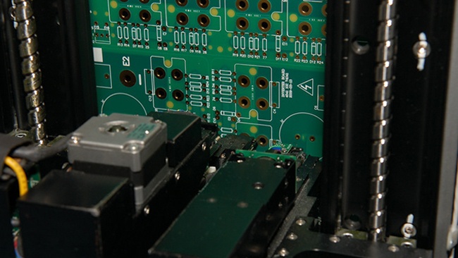
Flying probe electrically testing a circuit board
As higher-density PCBs go to production quantity, however, it becomes necessary to build a physical fixture, which is a somewhat time-consuming process. The test cycle using a fixture, while significantly faster than flying-probe, can still eat up time, depending on the number of points and nets which need to be verified. Special testing such as TDR for impedance, or Hi-Pot for demanding voltage levels, can further contribute to backups in the test department. As with other bottlenecks, some of these delays are simply the nature of the beast, so again it is extra important not to create additional bottlenecks in other departments, where you have more control.
Summary
In today’s competitive business climate, bringing your project in at a reasonable cost while meeting time-to-market goals is more important than ever. Designing your product for ease of production will give you your best shot at beating competitors to the punch. A steady, predictable delivery schedule makes it more difficult for “me too” products to gain a foothold. Don’t give your competitor the opportunity to introduce a substitute in the interim while your superior, but difficult-to-produce unit is out of stock because of preventable production delays.
Use every available resource to understand how you can design your product to be as good as it can be, without resorting to boutique manufacturing processes. Read, watch, and learn. Talk to your suppliers. Then hit the market confident that you will be able to respond to whatever demand arises.
Key Takeaways
- Designing for Manufacturability Saves Time and Cost: PCB designers should stay within standard process limits whenever possible to avoid redesigns, delays, and added expense caused by non-standard features that push beyond fabrication capabilities.
- Hands-On Learning Builds Better Understanding: Touring a PCB facility or watching in-depth production videos helps designers visualize each stage of fabrication, improving their ability to design boards that align with real-world manufacturing processes.
- Know and Use Standard Design Rules: Designers should rely on their fabricator’s published design rules and IPC standards for trace width, spacing, and hole sizes. Staying within these parameters ensures smoother production and consistent yields.
- Recognize and Avoid Production Bottlenecks: Processes like drilling, plating, routing, and electrical testing can become time-consuming if the design includes excessive tool changes, heavy copper plating, or tiny features. Simplifying these areas improves throughput.
- Collaborate Early with Fabricators: Open communication with your PCB supplier during the design phase allows potential problems to be identified and solved early, reducing lead times, avoiding costly revisions, and improving manufacturability overall.


