


When designing PCBs in a multi-up array, most designers choose v-score (also referred to as v score, v cut, or v groove) as the singulation method over traditional rout and breakaway tabs. The benefits of v-scoring pcb range from effortless removal of parts from panel form to realized cost savings with better utilization of panel area. When designing circuit boards in array with v-scoring, there are two areas of concern - the angle of the cut, and the depth of the cut.
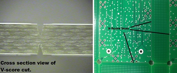
Cross Sectional View of a V-Score Cut and Broad PCB View.
Referring to the angle of the cut, the wider the angle makes it easier for part removal. A narrow angle will leave a thinner channel, allowing the designer more flexibility with image placement. A 30° angle is standard, which leaves a .015" channel, but thicker materials such as .093" or higher, may be better suited for the wider 60° angle. The depth of the scoring is measured by the remaining web thickness (groove center material left behind after scoring process). For standard laminates, at .062 thick, a .020" web thickness (+/-.004" tolerance) is recommended. For high temperature laminates, which tend to be brittle and fracture easily, a .015" web thickness (+/- .004" tolerance) is recommended for .062" thick laminates.

Challenges with V-Scoring PCB
V-scoring of printed circuit boards does come with challenges. If the parts do not breakout easily, it can lead to fracturing of the circuit boards during singulation, and also part dimension issues. These issues can be caused by a poor singulation process, incorrect PCB scoring specifications, or a quality shortfall at the actual scoring process.
Difficulty in breaking the parts from the scored array can be dependent on how the parts are removed from the array. In many cases manual hand separation is good enough to remove the assembled parts from the array. However, when the populated part leaves little room to sufficiently grasp the assembly, or the assembly uses a thicker laminate, a v-score cutter (pizza cutter) may be utilized. This cutter allows removal without unwarranted stress on the assembly itself.
When assemblies are difficult to remove, the forces placed on the assembly will cause what appears to be a haloing along the part edge. The haloing effect is the fracturing of the fiberglass bundles and resins of the base laminate. In a worst-case scenario, the separation will happen outside of the v-scoring channel and cause uneven breaks along the board edge. Possible causes for this issue can be incorrect score depth specification for the laminate used or rough part removal, placing excess stresses on the part. Inconsistencies with the scoring itself can lead to this. A dull blade or blades can cause the cut to be more of a "U" shape as opposed to the correct "V" shape.
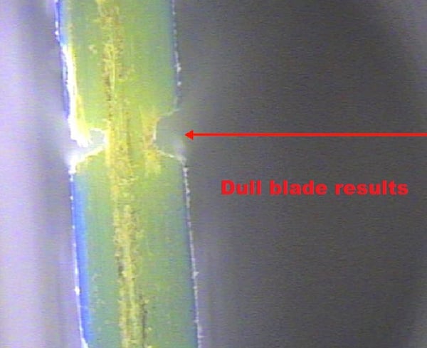
Poor Score Results with Dull Blade
This will increase difficulty in breaking out and leave excess material after singulation. An offset v-score - which is when one cut is deeper on one side of the part, due to blade settings, will also cause uneven and difficult singulation.
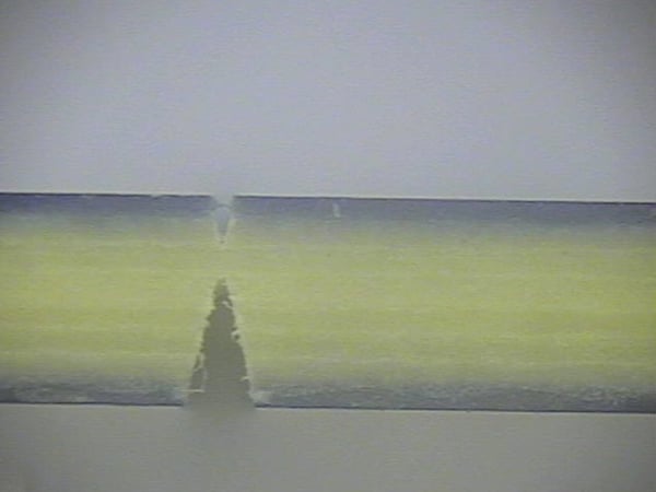
Printed Circuit Board Offset V-Score
Finally, we have seen some suppliers use a "milling" process or a controlled depth rout, as an attempt to replace actual score. When these parts are separated, there will be an excessive amount of material left over, that many CM's and OEM's will find problematic. This process is highly discouraged.
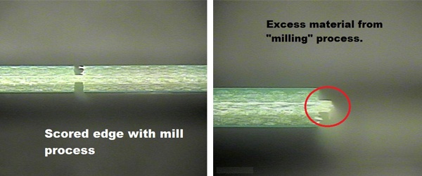
PCB Scored Edge with Milling Process
It is also important to note that with all v-scoring processes, there will be remaining laminate material on the part edge, after the parts are singulated.

PCB Scored Board Edge After Separation
Typically, the remaining material is too minute to affect the part fit, but if the design calls for a very low tolerance with unit fit, there could be an issue. Remember that if a part is scored on opposite edges, the remaining material on both sides can add up to enough that will cause a fit challenge in the final unit.
Make sure to download our free Technical Engineering & Design Guides which are packed with data from our high-tech manufacturing capabilities.
Key Takeaways
- V-Scoring Advantages: Preferred over route and breakaway tabs, v-scoring increases panel efficiency, lowers costs, and simplifies part removal.
- Cut Angle & Web Thickness: A 30° angle is typical for most designs, while thicker laminates may require a 60° angle. Standard web thickness for .062" laminates is .020", while brittle high-temp laminates should use .015".
- Common Challenges: Issues like fracturing, haloing, or uneven breaks usually stem from improper score depth, dull blades, or poor singulation practices.
- Removal Techniques: Manual hand separation works for many assemblies, but thicker or densely populated boards may require a v-score cutter to avoid stressing components.
- Supplier Practices Matter: Incorrect processes, such as milling in place of scoring, leaving excess material and poor results. Even with proper v-scoring, a small amount of laminate remains on the board edge, which can affect fit in tight-tolerance applications.


