


In simple terms, cable assemblies are comprised of two primary elements: the conductor and the connector. Rightfully so, the conductor’s sole purpose is to pass current at a given voltage, while the connectors job is to affix the cable assembly securely to a mating interconnect.
It’s clear that the conductor and connector garner most of the designer’s focus when designing cable assemblies, but sometimes the specific details of how to attach the connector to the wire are overlooked. For example, forgetting to purchase the appropriate crimp and extraction tooling for your custom cable build will delay your build, especially if these are long lead time or expensive tools. But what happens if three months into your program it’s determined that your specified connector was never meant to attach directly to a cable? What happens if the wire-to-board connector required must now be used as a wire-to-wire connector?

Wire-To-Wire Connector Systems
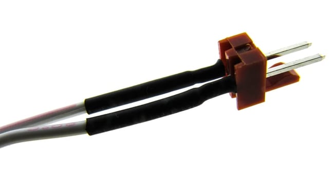
Most connectors have either a male or female gender. Connectors are also designed in wire-to-wire or wire-to-board systems to differentiate the application and installation requirements. Wire-to-wire connector systems are self-explanatory. The wires are affixed to the male and female sides of the connector using either a soldered or a mechanical connection to a jacketed wire. Your household extension cord is a simple example of a wire-to-wire system.
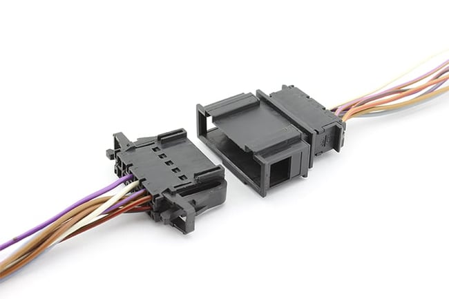
Example of a wire-to-wire cable assembly.
Wire-To-Board Connector Systems
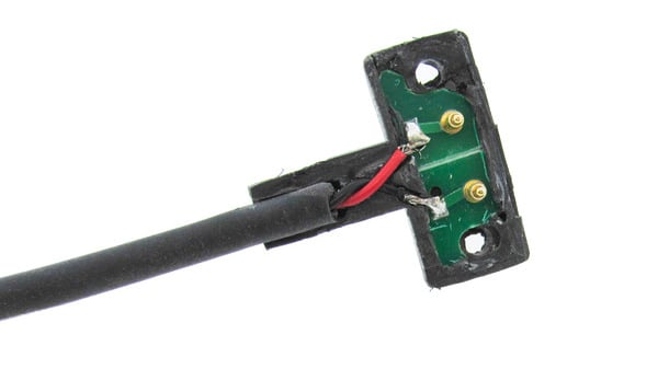
A wire-to-board connector system consists of a male and female set of connectors, with one being terminated to a cable harness and the opposite side being attached to a PCB (printed circuit board). Instead of using a crimp terminal and housing system, typically the “board” side of a wire-to-board connector system uses pins that are soldered to through holes or surface mounted to pads on the PCB.
This attachment methodology is extremely common in SMT (surface-mount technology) manufacturing. An everyday example of a wire-to-board connect system is the USB receptacle on your laptop that mates with your USB keyboard cable (just like what I am using today!).
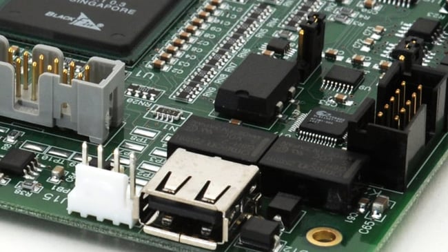
Example of a circuit board showing cables connectors.
Considerations Before Using A PCB-Mounted Connector Directly In Your Cable Assembly
If you find yourself scrambling to employ a PCB-mounted connector directly in your cable assembly, there are options to consider that may prevent a major design change. Before exploring some of the possible solutions on how to use a printed circuit board-mounted connector, it’s best to analyze the application and use case to completely understand the mechanical, environmental, and electrical requirement impacts.
- Ruggedization: Will your cable assembly be exposed to mechanical shock, vibration, or cyclic bending? Is there an expected amount of flexure that is required? Will the application have a pull strength requirement that may require strain relief? Knowing the qualification requirements or how the cable assembly will be used can provide the necessary details to select the best attachment option.
- Environmental: Some customer applications require resilience to certain chemicals or solvents, and others have ingress requirements like an IP66 waterproof rating. If a corrosion concern exists due to exposure to salt fog or other types of oxidation, this must be considered before selecting a design strategy. Other concerns such as UV exposure, temperature cycling, and prolonged exposure to humidity can also dictate the solution employed to terminate your PCB connector to your wire harness. These types of requirements can drive the design and manufacturing process utilized.
- Electrical: Low complexity headers and other surface mounted interconnect designs often have no need for shielding. It’s possible the application is passing low-voltage data, or the system is not susceptible to ESD (electrostatic discharge) or radiated emissions, reducing the need for shielding. Understanding if there are shielding requirements is critical before launching production. If the connector is intended to pass high-speed data or other another high-fidelity signal, this must be considered before selecting a design approach.
Design Solutions For PCB-Mounted Connectors In Your Cable Assembly
Once it has been determined that there are no other practical solutions to swap to a wire-to-wire connector solution, there are methods to use a printed circuit board-mounted connector directly in your cable assembly. All headers and similar PCB connectors have a series of pins or similar contact pads that could work in a cable, but three critical design requirements must be explored:
- The header pins must be electrically connected to the cable conductors
- The header pins must be electrically insulated from one another and the adjacent cable conductors
- The appropriate amount of strain relief must be designed into the solution
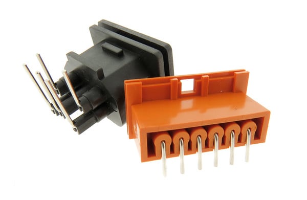
PCB-mounted connectors with pins shown.
Solution #1: Lap Solder
A lap-soldered connection is a common type of soldering operation that is ideally suited for low-complexity designs with benign environmental requirements. To perform this, the surfaces must be cleaned, and the cable insulation must be stripped, leaving an overlapping section of the header pin and the bare cable conductor. The two members are then soldered together to create the electrical connection; the solder acts as a pseudo-weld to provide strength.
Lap-soldered connections are feasible since the header pins and bare conductor can easily overlap one another, creating the framework to quickly perform the lap-solder operation. Heat shrink tubing can then be applied to the exposed conductors, providing a means of electrically insulating the components.
Why this is important: Lap-soldered connections are best for applications with no or minimal movement. Using different types of heat shrink (thickness, adhesive lined) offers slight improvements to pull strength and motion.
Tip: Due to the lap-soldering process requirements and difficulties soldering to fine pitch connectors, the smallest recommended pin pitch is 2.45mm (0.100”).
Lap-soldered header with cable harness.
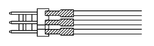
Solution #2: Wrapped Wire And Soldered
Like the lap-soldering process, using a wrapped wire and soldered connection is another technique to consider when attaching a bare wire conductor to a PCB-mounted connector pin. Instead of using an overlapping section of conductor and header pin, the bare wire is wrapped around the header pin like a post. Typically, one to four wraps are necessary before applying solder. This type of connection is stronger than a lap-soldered connection, since the wire is coiled around the header pin before soldering.
Why this is important: Although it is stronger, this type of soldered connection is only appropriate for applications with little or no movement.
Tip: Similar to the lap-soldering process, the smallest recommended pin pitch is 2.45mm (0.100”). The wire AWG size will also impact this since only small AWG sizes can be used to coil around the header pins.
Example of a wrapped wire and soldered connection.
Solution #3: Intermediary PCB
If strength and reliability are critical, both lap-soldered and wrapped-wire connections are not appropriate for the application. Assuming there is physical space, the addition of an intermediary circuit board is the best option for a robust design solution. A low-complexity PCB of typically one or two layers would need to be designed in a way that would allow the header pins to be affixed and soldered. The PCB would be designed such that the header pin traces would electrically connect to corresponding plated through holes, and then soldered to the bare conductors of the cable harness. Next, the intermediary PCB must be electrically insulated and encapsulated for strength.
Why this is important: This process contains more components, more operations, and is more expensive. The intermediary PCB design solution is preferred when a high reliability or robust connection is needed.
Tip: If passive devices like LEDs, resistors, or tactile switches are being considered elsewhere in the assembly, adding them directly to the intermediary PCB can provide added functionality without a significant cost impact.
Example of a cable assembly with intermediary PCB.
Don’t Forget The Overmold
Once the attachment methodology is determined, your application may benefit from a custom over molded connector. Custom overmolds and strain relief options in cable assemblies offer a wide variety of low-cost customization once the tooling is designed. Overmolded connectors require hard tooling to be designed and built and provide exceptional strain relief and electrical insulation for the delicate connections discussed in this post.
The first step is to design an inner mold of a high durometer and electrically insulating material. The design intent of the inner mold is to provide a high strength means of encapsulating the components. The outer mold is typically a softer material and provides both strain relief and a cosmetic surface.
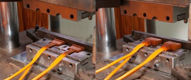
Example of a cable assembly inner mold (left) and outer mold (right).
Summary
It’s clear that advanced planning for any new development program is critical, and the failure to take heed of critical design details such as the difference between a wire-to-wire and wire-to-board interconnect system can wreak havoc on a development schedule.
If you find yourself in this situation where there are issues using a PCB-mounted connector in your cable assembly, there are options that will not completely derail the project.
Understanding the specific manufacturing techniques and limitations is vital and will help enable the rapid resolution to these types of development challenges or delays.
Key Takeaways
- Understanding Connector Types: Wire-to-wire connectors attach wires directly, while wire-to-board systems connect cables to a PCB via male and female connectors, commonly used in SMT manufacturing.
- Considerations for PCB-Mounted Connectors: Key factors include:
- Ruggedization: Assess mechanical stress, vibration, and strain relief requirements.
- Environmental Conditions: Consider exposure to chemicals, humidity, temperature cycling, and ingress protection needs.
- Electrical Requirements: Evaluate shielding, signal fidelity, and ESD susceptibility.
- Lap-Solder Connections: Best for low-complexity designs with minimal movement, this method involves overlapping wire conductors with header pins and securing them with solder and heat shrink tubing.
- Wrapped Wire Connections: Wrapping wires around header pins before soldering offers a stronger connection than lap-soldering but is still limited to low-movement applications.
- Intermediary PCB for High Reliability: Using an additional PCB provides robust connections for critical applications. This solution supports complex designs and allows the integration of passive components like LEDs or switches.
- Custom Overmolding: Overmolds provide exceptional strain relief, durability, and electrical insulation. Combining a hard inner mold for strength with a softer outer mold enhances functionality and aesthetics.
- Advanced Planning is Critical: Failing to account for connector type and attachment details early in the design process can lead to delays, costly rework, or functional issues.
- Options for Design Challenges: When PCB-mounted connectors must be adapted for cable assemblies, manufacturing techniques like lap-soldering, wrapped wires, or intermediary PCBs can resolve challenges without derailing the project.


