


Most test engineers agree that if you were to make a list of the major causes of compliance failures for most of the electronic products we use in our daily lives, radiated emissions (RE) would, undoubtedly, be right at the top.
At their core, radiated emissions tests are straightforward, they monitor and characterize any and all unintentional electromagnetic energy releases coming from an electronic device. This device can be a box build, PCBA, or even a cable assembly. (Note: cable assemblies are passive devices and do not create their own electrical fields). Emissions tests are the most common type of EMC tests done worldwide. The criticality of unwanted electrical interference and the potential risks associated with undesired operation have created emission limits and other standards that have been established on a global capacity across all industries. Any failure during radiated emissions testing may delay or prevent the final qualification and impact the devices eventual release to production.
It's also important to note that the creation of electrical fields that are measured during radiated emissions tests are largely inherent to most electronic products by design. Thanks to switching voltages, high speed data transmission, and electrical field formation due to the flow of electrons, electrical devices emit radiated energy. Therefore, the goal of radiated emissions testing isn't to verify that these emissions aren't happening at all. Instead, the goal of the test is to answer the question "does your product comply with the emissions limits as they exist today?"

For the purposes of these tests, digital devices are separated into two distinct classes: A and B. Class A devices are those that will be used in a commercial, industrial, or business environment, while class B devices are those intended for residential use. Radiated emissions tests are particularly essential in the former category. If you were to bring an electrical device that is emitting high levels of radiated electromagnetic energy into an environment like a hospital, this device could potentially interfere with life-saving equipment that also exists in the same space. For this same reason, prior to aircraft taxi and departure, passengers are required to power down potentially interfering electrical devices. While there is debate over airlines’ policies to limit some, but not all, electrical devices, the overarching goal is to minimize any risk of catastrophic interference between your smartphone and critical systems onboard the aircraft. There are other and less dire consequences of electrical interference attributed to radiated emissions and these typically consist of undesired operation, power down events, and situations like data loss or hardware failure. A careful assessment of the application and corresponding radiated emissions limits must be considered early in the design phase but understanding the test conditions and setup itself is equally important./p>
Typical Radiated Emissions Test Setup Breakdown
Radiated emissions testing tends to be a bit more complicated in nature than other EMI/EMC tests such as ESD or conducted emissions and, as a result, the typical test setup reflects that complexity. Radiated emissions setups includes a sensing antenna paired with an analyzer. The analyzer is tasked with scanning across a predetermined frequency band while measuring the amplitude of the electromagnetic energy. The antenna will scan the frequency band of interest, typically 9 kHz to 30 MHz depending on the specific regulation, but the frequency range can also extend to up to 6 GHz or higher. The receiving antenna measures emissions radiating from the device, or UUT (Unit Under Test). The height of the antenna is also critical and is usually between 1 and 4 meters. The antenna may rotate for a given test condition in both a horizontal and vertical orientation, this can impact the magnitude of measured frequencies due to the polarization of the electromagnetic waves. The measurement units for radiated emissions are usually dB or dBa (which is a logarithmic scale). These measured values are compared with established industry limits that can be taken directly from existing specifications such as Mil-STDs or other compliance requirements to determine the eventual pass/fail conclusion.
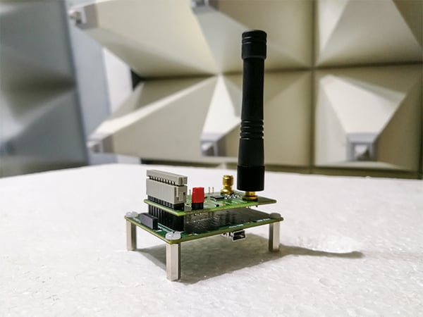
Example of Typical Radiated Emissions Test Setup
There are two main types of radiated emissions test sites to consider: an open area test site (otherwise known as an OATS), or a semi anechoic chamber.
Open Area Test Site
The first, an open area test site, is an extremely common type of radiated emissions test site and is designed with no reflective or absorptive features and may avoid metallic or conductive building materials all together. This helps replicate the desired test conditions and is usually performed at test distances of 3 meters, 10 meters, or 30 meters. OATS sites are “outside” and may pick up ambient or naturally occurring electromagnetic energy.
Semi Anechoic Chamber
The second, a semi anechoic chamber, is essentially the same concept as an OATS, only instead of being outside, the site is housed within a shielded metal room creating a faraday cage. This construction is necessary as it allows test engineers to distinguish background signals from those coming from the UUT. The inside walls of the semi anechoic chamber are lined with a special type of RF absorptive foam or other materials. This design keeps all reflected signals to a minimum while eliminating all outside interference from impacting the test measurements. Standing within a properly shielded anechoic chamber will sound acoustically dead, with no echo nor reverberation. Your cellular phone and Wi-Fi signals will also be rendered useless within an anechoic chamber- take note if you need Wi-Fi to run your UUT!
A semi anechoic chamber largely operates in the same way to an open-air test site as far as the actual test is concerned. Both test setups involve an antenna, an analyzer, and a UUT. Anechoic chambers tend to be expensive (most are built for more than $100K), so building your own shielded room for radiated emissions testing may not be feasible. But they are an ideal solution for measuring radiated emissions in environments that are particularly noisy. In those situations, an OATS would likely provide an inaccurate radiated emissions signature for your UUT.
Radiated Emissions Test Specs to Be Aware Of
Radiated emissions testing applies to electronic and other digital devices of all types and in all industries. If your product doesn't pass, this can prevent you from obtaining the final industry approvals necessary to release your device to market. Listed below are the typical industry specifications that include radiated emissions testing.
- Mil-STD-461: As the name suggests, this is a United States Military Standard that is applicable to all products used by the men and women of the Armed Forces. Additionally, many civilian businesses adhere to this specification, even though they don't technically have to. Radiated emissions testing per Mil-STD-461 is usually done in an anechoic chamber and this is by far one of the strictest standards for electromagnetic compatibility in existence.
- RTCA-DO/160: First published in 1975, this specification applies to airborne equipment and, as a result, has become the standard for radiated emissions testing for commercial aerospace and avionics hardware. This is also a very strict spec as it helps establish limits of electromagnetic interference on passenger aircraft.
- CISPR 11: This is the analog standard to EN 55011, which itself is a European standard that oversees everything from household appliances to medical devices and absolutely everything in between. For the most part, it's used in conjunction with industrial, scientific and medical (ISM) radio-frequency equipment.
- CISPR 12: This standard applies to vehicles, boats, and any other types of craft with an internal combustion engine. It looks for radio disturbance characteristics and helps take a closer look at limits and method of measurement. While this is used by the automotive industry, it's also important to note that most OEMs (original equipment manufacturers) have their own sets of internal standards that they also use.
- IEC EN 61000-4-3: This specification involves both the testing and measurement techniques for radiated, radio frequency, and electromagnetic field immunity tests. The goal behind the creation of this specification was to establish a common reference of a product or device to radiate RF immunity, in particular, that is caused by other devices that may be in the area like walkie talkies or modern-day smartphones. It covers the 80 MHz to 1 GHz frequency range.
Radiated Emissions for Cable Assemblies
Since cable assemblies are usually passive devices, the radiated energy being emitted from cable assemblies can be mitigated by several techniques. Listed below are some to consider when facing a radiated emissions test for your cable assembly.
Component Shielding/Modification
The first option is to address the source of the electrical noise. This can be achieved by reviewing the electrical circuit and isolating noisy components. Employing an alternate PCBA relay or noisy power supply may solve your problems.
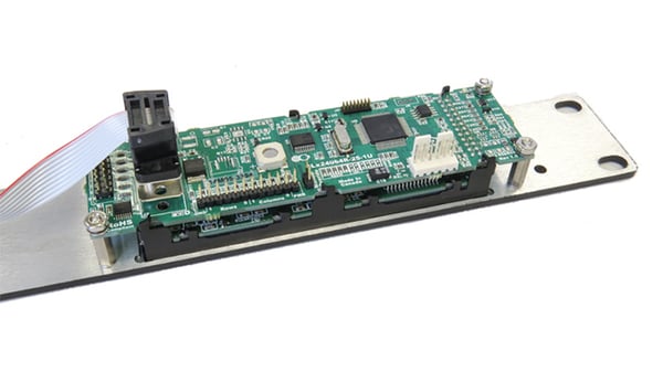
PCBA Components Can Be the Source of Electrical Noise Causing Radiated Emissions Failures
Ferrites
If swapping alternate PCBA components is not possible or doesn’t fix the issue, the next step is to attempt to attenuate the noise along its transmission path. The most common technique is to employ an RF absorptive component in your cable design, such as a ferrite. These annular magnets fit around cable bundles and are tuned to a specific frequency range and help filter unwanted RF energy in your cable assembly. Sometimes, including multiple wraps or loops can help filter additional frequencies or lower the overall radiated emissions levels.
Shielding
Shielding bulk cable or individual conductors is an extremely effective way to address radiated emissions noise. There are different types of shielding that range from a woven overbraid, to copper tape, and metallized foil wraps. All have their unique benefits so it’s best to review the design goals with your cable manufacturer to help best recommend the ideal shielding strategy. Sometimes, industry standard wire comes with an existing shielding technique, though this may not be enough for your application. Although custom runs of shielded wire are possible, they may carry high minimum order quantities that may not practical for your project.
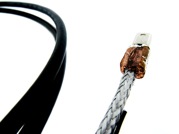
Cable Assembly Shielding with Metallized Foil Wraps
Summary
Radiated emissions testing is one of the most common and critical steps in ensuring electronic devices, including cable assemblies, meet compliance standards. These tests measure unintentional electromagnetic energy released from a product to determine whether emissions fall within established regulatory limits.
Depending on the application, testing may be performed in open area test sites (OATS) or semi-anechoic chambers to accurately characterize emissions. Standards such as Mil-STD-461, RTCA-DO/160, CISPR 11/12, and IEC EN 61000-4-3 set the requirements for industries ranging from military and aerospace to automotive and medical devices.
Since cable assemblies can conduct and re-radiate emissions even though they are passive, engineers often employ design solutions such as improved component selection, ferrite filters, or shielding techniques to ensure compliance. Addressing these factors early in the design phase helps prevent costly delays, failed tests, and compliance-related setbacks.
Key Takeaways
- Radiated emissions are a leading cause of compliance failures and must be addressed early in the design cycle.
- Cable assemblies, though passive, can re-radiate noise from connected devices and contribute to test failures.
- Testing is performed in OATS or semi-anechoic chambers, with antennas scanning across frequency ranges up to 6 GHz or higher.
- Multiple global standards (Mil-STD-461, RTCA-DO/160, CISPR, IEC EN 61000-4-3) dictate emissions limits depending on the industry and application.
- Mitigation methods like component changes, ferrite filters, and shielding are essential tools for reducing unwanted emissions and ensuring product approval.


