


Front panels, bezels, and other types of human to machine interface equipment use several circuit technologies to operate. These circuit types usually involve some form of printed or etched traces using conductive materials like copper and conductive ink. These custom layouts are routed across insulating sheets and films, eventually becoming circuit boards and flex circuits. Dome switches, LEDs, and touchscreens can be added to these everyday circuit boards, bringing them to life as a high-technology HMI solution.
When designing a front panel, there are numerous design variables to consider. First, there is artwork that can be displayed across your front panel using custom printing on durable hard-coated films. Another important consideration when designing a front panel are the number of switches, how they operate, and how the switches are wired into the system. Dome switches are one option, and off-the-shelf tactile switches are another option that offers special functionality. Another consideration for a front panel is the backlighting and LED selection. This will help guide the user to properly operate the device while making it legible in daylight and darkness. But one of the most critical design criteria, and sometimes the most overlooked, is how to connect a wire or cable to your HMI front panel. This is especially true if a rigid PCB is going to be used.
Listed within this blog post are 3 options for connecting to your rigid PCB front panel.

Option 1: Surface-Mounted/Through-Hole Connector
One of the best ways to connect a wiring harness to a rigid printed circuit board is to use a wire-to-board connector system. This method offers a high reliability mounting solution, but will incur the costs of the mating connectors, crimp terminals, and any tooling required for assembly. There are countless types that provide the range of configurations and options. Many of the name brand electronics’ manufacturers, such as Molex, TE, and Samtec, all offer their own line of connectors designed to interface with circuit boards.
The first step to selecting the best connector is to determine the number of circuits (or pins). Many connector families are arranged in single row and double row designs. If 40 or more circuits are required, this may require a specialty interconnect with a fine pitch (the space between pins) design.
Next is to determine the connector orientation. Due to clearance and space constraints, a vertical or right-angle connector will be chosen. It is important to make sure the mating connector has enough clearance, especially when installing a right-angle connector near surface-mounted components like resistors and capacitors. Finding an interference fit once the PCBA is assembled will likely drive a respin or major design change.
Once the connector size and orientation style are selected, the rest of the connector details can be chosen. Many of these manufacturer offered features are merely to address reliability and performance concerns. These features include polarization, locking features, specialty pin materials/coatings, and more.
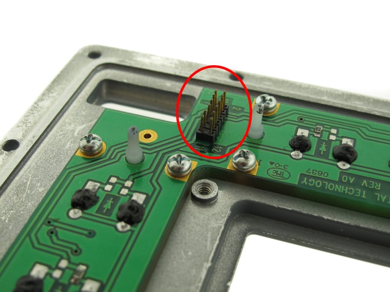
Dual row wire-to-board header system.
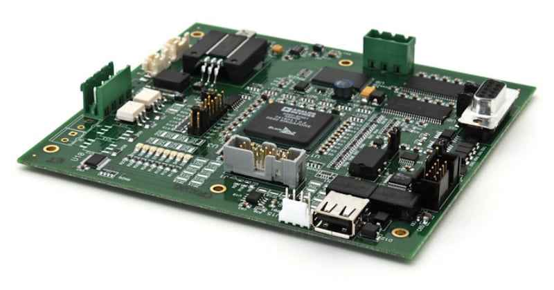
PCBA with numerous wire to board connectors.
Option 2: Wire Harness Soldered Direct to PCB
For applications with a simple cable interface, or where cost is a critical concern, dedicated cable connectors can be nixed for a soldered connection direct to the PCB. This simple approach is effective and appropriate for about 10 wires or less, low-voltage applications, and where ruggedization is not a concern. Usually these soldered wires provide 5VDC power, low-speed data, or switch and LED control. The solder joint is not as strong as a crimped wire connection, and the joint is mechanically weak. There are some clever assembly ways to reinforce this connection like RTV sealant, or shaping the wire’s conductor, but it’s inherently less strong than a wire-to-board type connector. This technique should be avoided where vibration, flexure, or any type of mechanical load is expected.
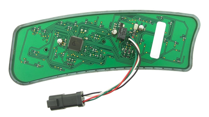
Wire harness soldered direct to a printed circuit board.
The first step to designing this interface is to study the wire cross section and the areas available to mount on the circuit board. The PCB should be designed with thru holes or pads sized to the wire conductor. Fine wire sizes like 32AWG and smaller diameter are too delicate for this method and should be avoided. Large wire sizes can be equally as challenging to properly shape and solder and should be avoided. Silkscreened artwork and other markings can be applied to the bare PCB noting the wire’s polarity or jacket color. This additional marking step will help both assembly and inspection.
Flat flexible cable soldered to a printed circuit board.
Option 3: Use a Separated Membrane Switch
If you are stuck on the best way to integrate a connector onto your rigid PCB front panel, the best option may be to split the keyboard design from the PCBA. There are several challenges when designing and assembling custom membrane switch panels, especially on rigid PCBs.
If a dome switch is chosen as the switch technology, designing the surrounding layers of the circuit can be complex. Several layers of adhesive, sheet spacer material, and custom printed circuits are sandwiched together surrounding the dome switch locking it into place. The dome switch must also be able to compress supporting switch function. These layers are carefully designed, embossed, and die cut to provide the proper functionality. These critical steps in the design and assembly process help with button performance, uniform backlighting, and overall reliability of the switch.
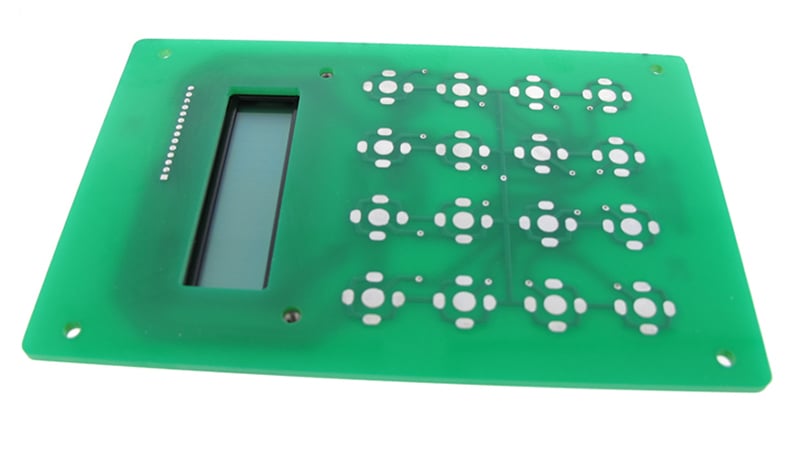
Dome switch pads on a PCB.
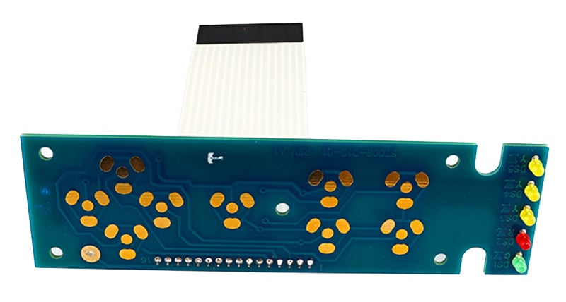
If integrating a series of dome switches into your front panel proves risky, this key matrix and LED portion of the design can be built separately and then adhered onto the rigid PCB with sheet adhesive or mounting studs. Essentially, you are separating the keyboard and LEDs of the front panel onto a dedicated low complexity circuit. This standalone membrane switch can connect to your PCB with an ordinary header or ZIF connection. While this does create an additional subassembly in your project, there are numerous benefits to this approach, including less board respins and a reduced overall timeline.
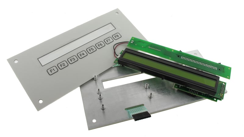
Rigid PCBA with separated membrane switch keypad.
Getting Started with your Rigid PCB Front Panel
One of the benefits of a full-service manufacturing partner like Epec is we understand both the development process and the manufacturing details of custom engineered products like HMIs, membrane switches, and complex PCBAs.
Early engagement with a supplier like Epec can help steer the design toward a high-reliability, low-cost solution. Additionally, getting stuck in the details of HMI front panel design can be an exhausting task, especially if it’s not a core competency. By providing the overall program and design objectives, a company like Epec can provide a turnkey quotation and deliver a high-value product. Let us worry about the internal layers, their materials, their thickness and the overall construction.
Key Takeaways
- Wire-to-Board Connectors Offer Reliability: Using surface-mount or through-hole connectors is the most reliable option, but it adds cost due to mating connectors, crimp terminals, and tooling. Proper pin count, pitch, and orientation selection (vertical or right-angle) are critical to avoid clearance issues and potential redesigns.
- Direct Soldering Is Low-Cost but Less Durable: Soldering wires directly to a PCB is cost-effective and suitable for simple, low-voltage applications with fewer than 10 wires. However, the mechanical strength is weak compared to crimped connections, and this method should be avoided in environments with vibration or mechanical stress.
- Membrane Switch Separation Provides Design Flexibility: For complex HMI panels, separating the membrane switch and LEDs into a standalone subassembly can simplify integration. This approach reduces design risks, minimizes respins, and allows connection to the main PCB through standard headers or ZIF connectors.
- Mechanical & Electrical Considerations Are Crucial: When choosing between connectors, soldered wires, or membrane subassemblies, engineers must weigh factors such as signal type (low current vs. high current), durability, assembly complexity, and the risk of board respins. Early design planning avoids costly mistakes later.
- Early Supplier Engagement Reduces Risk: Partnering with a full-service supplier early in the HMI design process helps balance performance, reliability, and cost. Suppliers can recommend the best interconnect approach, optimize stack-up and material selection, and provide turnkey solutions to speed time-to-market.


