


When tackling any new project, it’s human nature to focus on the most difficult and uncertain tasks first, while leaving the perceived low-risk and simple activities for the end. When it comes to developing a new product, whether it be for a medical device, commercial widget, or even a mil-aero box build, the initial focus is on the major system elements.
Typically, custom machined members, printed circuit board assemblies (PCBAs), and large expensive commercial off-the-shelf (COTS) items receive most of the focus early on. This leaves items such as labels, fasteners, hardware, and especially cable assemblies pushed to the tail end of the development cycle. But this isn’t necessarily due to someone’s procrastination. Rather, this is the result of several underdefined system requirements that simply aren’t ready for the detailed design phase. For example, will your TFT display require an HDMI or a low-voltage differential signaling (LVDS) interface? Will your system be operating off 3.3VDC or 28VDC? Will you need a 12” cable length or 32” cable length? It is tough to answer these questions as you are still evaluating options while drawing on the backside of a napkin.

It’s all too common for cable assemblies to be one of the last specified items. If the cable assembly necessary to wire up your system can be bought off the shelf, waiting until the end of your design cycle to specify these items is wildly practical. But what if your required cable connector has a long lead time, or does the strain relief need a custom overmold tool? It’s not uncommon for specialty connectors to carry a 16+ week lead time, or a custom overmold tool to take up to 8 weeks to prove out. Sometimes components are available, but critical assembly tools such as crimpers or extraction tools are the long pole in the tent. The failure to account for these timelines for critical path hardware items will add cost, time, and headaches to any development program. Should you find yourself in this situation, listed within this post are 5 tips to consider before it’s too late.
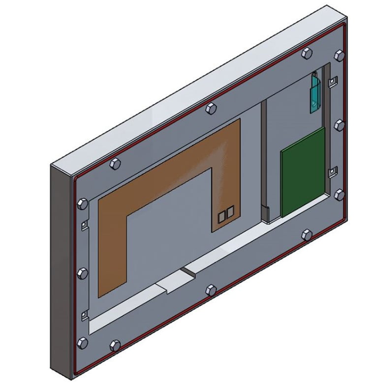
Proof of display concept with cable assemblies omitted.
1. Define Critical Interconnects and Connector Types Early
As soon as possible, all critical interconnects and connector types must be identified. If there are any environmental or qualification requirements that would drive the connector selection, this must be reviewed during the program launch phase. For example, if your application requires a sole-sourced connector, EMI shielding, or an IP-rated waterproof connector, these are at risk for long lead times.
2. How Many Do You Need and What are You Doing with Them?
There can be enormous lead time swings between a 2 pcs sample run and a 1,000 pcs production volume. Often, the 2 pcs sample run can be fabricated using non-production style tooling that is comparable to rapid prototyping. These items are generally laid up and assembled by hand using bench-top hand tools. This process is comparable to a quick-turn build plan when compared to a 1,000 pcs production run that has several machine setups and tear down operations.
3. Use 3D Printing for Non-Electrical Fit Check Prototypes
For projects where an overmolded cable must pass through a panel or bulkhead, engineers will establish critical dimensions and clearances for their design specification. Waiting 6-8 weeks for a custom overmolded cable to facilitate fit checks is unacceptable and can create significant risk. In addition, many new ideas and programs are launched at trade shows using marketing samples that are non-functional dummy units. Consider using 3D-printed samples and dummy connectors where appropriate if all that is needed is a “show n’ tell” device.
4. Get Creative and Employ All Available Resources
If your program requirements allow, there are numerous creative approaches to reduce program risk early on by employing a proof-of-concept type cable assembly with readily available materials. For example, with less than $40 worth of materials and common cables in your office, a 28AWG shielded USB cable can be fabricated to test your prototype board (just cannibalize a few phone chargers or keyboard cables). If a quick and dirty overmold concept is required, ordinary RTV and a 3D-printed mold can be used to produce a proof of concept for your overmolded breakout or strain relief.
5. Engage your Manufacturing Partner Early
Full-service manufacturing partners like Epec can offer consultation on all aspects of bringing a custom cable assembly to market that include sourcing, design, manufacturing as well as the logistics of getting your custom cable assembly built and shipped.
Early discussions regarding program constraints allow companies like Epec to recommend options to mitigate risk and establish clear delivery expectations once production commences. For example, if an industry standard connector such as an RJ45 is to be used, there is already house overmold tooling in place with Epec which can save cost and weeks off your schedule. But this house tooling can only be used if the design requirements permit its use.
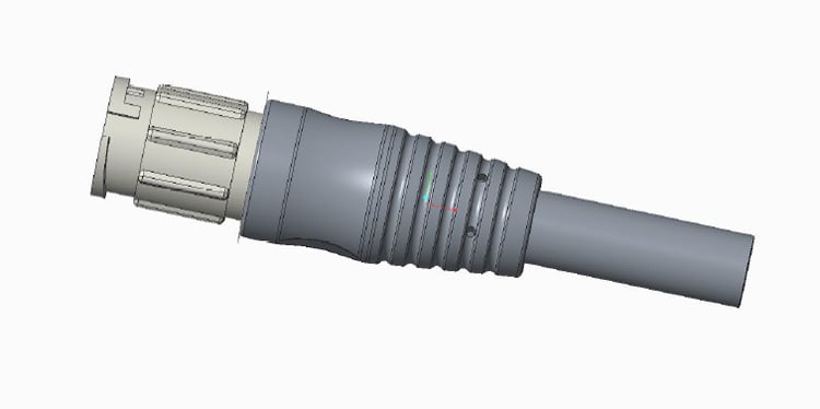
Example of a custom overmold 3D model.
Summary
There is not much worse than being designed into a corner, leaving no options but to stomach a long lead time component, or failing to account for the manufacturing lead time for a custom cable assembly. These issues eventually lead to companies hemorrhaging cash to accelerate a poorly planned development schedule.
These scenarios also put undue pressure on your supply chain partners to recover lost time and trim cost. At the very least, holding a 30-minute conference call with a company like Epec can help to understand the various moving parts required to bring a custom cable assembly to market before it’s too late.
Key Takeaways
- Define Interconnects Early: Identify all critical connectors, environmental requirements, and qualification needs at the start of the project to avoid long lead times and design delays.
- Plan for Quantity and Timing: Understand the difference between prototype and production builds, small sample runs can be quick, while large production volumes require more setup and lead time.
- Use 3D Printing for Fit Checks: Employ 3D-printed connectors or mockups to verify fit and function early, minimizing delays while waiting for custom overmolded components.
- Leverage Creative Prototyping: Use readily available materials, simple molding methods, or off-the-shelf cables to create early proofs of concept and reduce program risk.
- Engage Manufacturers Early: Collaborate with experienced partners like Epec during the planning phase to access existing tooling, reduce costs, and ensure realistic delivery timelines.


