


When it comes to selecting the appropriate cable type for a multi-conductor , there seems to be an endless combination of wire sizes, jacket materials, conductor arrangements, and shielding methodologies.

Multi-conductor cables also come in a variety of colors and the ability to mix and match wire sizes within the bundle. This means that there are countless options available, making it difficult to select the absolute best option. This is especially true if there are low voltage differential signals (or LVDS pairs) involved.
Multi-Conductor Cable Options
The below table is an example of flexible multi-conductor cable options for 22AWG through 26AWG.
| Item | Number of Cond. | AWG Size | Strand Constr. | Nominal Wall Thick. | Nominal Diam. | Shield Strand AWG |
|---|---|---|---|---|---|---|
| 1 | 5 | 22 | 65/40 | 0.01 | 0.049 | |
| 2 | 5 | 22 | 65/40 | 0.01 | 0.049 | 40 |
| 3 | 5 | 22 | 65/40 | 0.01 | 0.049 | |
| 4 | 5 | 22 | 65/40 | 0.01 | 0.049 | 40 |
| 5 | 1 | 22 | 150/44 | 0.01 | 0.049 | 44 |
| 6 | 1 | 22 | 150/44 | 0.01 | 0.049 | 44 |
| 7 | 2 | 22 | 150/44 | 0.01 | 0.049 | |
| 8 | 2 | 22 | 150/44 | 0.01 | 0.049 | 40 |
| 9 | 2 | 22 | 150/44 | 0.01 | 0.049 | |
| 10 | 2 | 22 | 150/44 | 0.01 | 0.049 | 40 |
| 11 | 3 | 22 | 150/44 | 0.01 | 0.049 | |
| 12 | 3 | 22 | 150/44 | 0.01 | 0.049 | 40 |
| 13 | 3 | 22 | 150/44 | 0.01 | 0.049 | |
| 14 | 3 | 22 | 150/44 | 0.01 | 0.049 | 40 |
| 15 | 4 | 22 | 150/44 | 0.01 | 0.049 | |
| 16 | 4 | 22 | 150/44 | 0.01 | 0.049 | 40 |
| 17 | 4 | 22 | 150/44 | 0.01 | 0.049 | |
| 18 | 4 | 22 | 150/44 | 0.01 | 0.049 | 40 |
| 19 | 5 | 22 | 150/44 | 0.01 | 0.049 | |
| 20 | 5 | 22 | 150/44 | 0.01 | 0.049 | 40 |
| 21 | 5 | 22 | 150/44 | 0.01 | 0.049 | |
| 22 | 1 | 24 | 105/44 | 0.01 | 0.044 | 44 |
| 23 | 1 | 24 | 105/44 | 0.01 | 0.044 | 44 |
| 24 | 2 | 24 | 105/44 | 0.01 | 0.044 | |
| 25 | 2 | 24 | 105/44 | 0.01 | 0.044 | 44 |
| 26 | 2 | 24 | 105/44 | 0.01 | 0.044 | |
| 27 | 2 | 24 | 105/44 | 0.01 | 0.044 | 44 |
| 28 | 3 | 24 | 105/44 | 0.01 | 0.044 | |
| 29 | 3 | 24 | 105/44 | 0.01 | 0.044 | 40 |
| 30 | 3 | 24 | 105/44 | 0.01 | 0.044 | |
| 31 | 3 | 24 | 105/44 | 0.01 | 0.044 | 40 |
| 32 | 4 | 24 | 105/44 | 0.01 | 0.044 | |
| 33 | 4 | 24 | 105/44 | 0.01 | 0.044 | 40 |
| 34 | 4 | 24 | 105/44 | 0.01 | 0.044 | |
| 35 | 4 | 24 | 105/44 | 0.01 | 0.044 | 40 |
| 36 | 5 | 24 | 105/44 | 0.01 | 0.044 | |
| 37 | 5 | 24 | 105/44 | 0.01 | 0.044 | 40 |
| 38 | 5 | 24 | 105/44 | 0.01 | 0.044 | |
| 39 | 5 | 24 | 105/44 | 0.01 | 0.044 | 40 |
| 40 | 1 | 26 | 66/44 | 0.01 | 0.039 | 44 |
| 41 | 1 | 26 | 66/44 | 0.01 | 0.039 | 44 |
| 42 | 2 | 26 | 66/44 | 0.01 | 0.039 | |
| 43 | 2 | 26 | 66/44 | 0.01 | 0.039 | 44 |
| 44 | 2 | 26 | 66/44 | 0.01 | 0.039 | |
| 45 | 2 | 26 | 66/44 | 0.01 | 0.039 | 44 |
| 46 | 3 | 26 | 65/44 | 0.01 | 0.039 | |
| 47 | 3 | 26 | 65/44 | 0.01 | 0.039 | 44 |
Low voltage differential signaling is a term used to describe electronic information that is carried using two separate but complementary conductors. Each signal uses its own wire within a twisted pair of cables. The actual twisting of the pairs around one another helps create improved signal quality. As the number of twists per inch increases, the data transmitting properties of the cables can be improved.
Typically, LVDS applications require wire sizes such as 28AWG to 32AWG, with some projects demanding even finer gauge wire options up to 38AWG. These miniature wire sizes enable fine pitch connectors to be used, and at times dozens of pairs to be contained within one bundle. High-density circuits using LVDS bundles can be developed for data transmission and high-resolution video applications.
The majority of multi-conductor cables contain less than 10 individual conductors. These legs are somewhat randomly layered within the cable bundle. The outer jacket and filler material are then wrapped around the bundle creating the final cable construction. If LVDS signals are required, using an ordinary bundled cable cross section with be insufficient and the differential signals will be compromised.
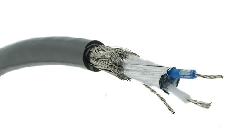
Example of a twisted pair with shield + drain wire.
Each individual LVDS signal must have a dedicated twisted pair of conductors within the cross section. For an LVDS signal to be used within a multi-conductor cable, there must be individually twisted pairs that are within the bundle. For some applications, individually shielded twisted pairs are required. The inner shield layers for these designs typically consists of a metalized foil, which is like the overall foil shield of a standard data cable.
When to Use LVDS Pairs in Your Multi-conductor Cable
Using differential signaling within multi-conductor cables provides several benefits. The primary reason for employing a differential signal is to help mitigate the impacts of electromagnetic interference (EMI). Because the transmitting signal responds to the difference in voltage between the two signals within the pair, the interference or crosstalk between the two legs is cancelled out. This results in a cleaner signal and can be the difference between a clear and a blurry video image.
Additionally, differential signaling offers benefits for lower-voltage circuits. In a single-ended transmission, those signals must maintain a large potential to support the required signal to noise ratio (SNR). Differential signaling allows for lower supply voltages to be used which helps the overall efficiency of the cable.
It is common to include LVDS pairs into the cross section of a multi-conductor cable. This is especially true for applications that require both power and data. For many low-voltage circuits that are running on less than 30V, the cable can be designed with a uniform cross section that offers the same wire size for all legs. For other projects, the power leads may need to be sized larger than the LVDS pair. For this instance, the required current draw is likely too high for the LVDS pair wire size.
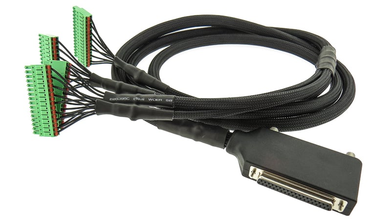
Multi-conductor cable assembly with LVDS pairs.
Some multi-conductor cables only contain LVDS pairs. This is common for the serial ATA cables that are used to connect computer hard drives. These high-performance data cables are capable of transmitting data at rates of 1.5 - 2.5 Gbit/s. When these cables are bundled together with additional pairs, their data transfer speeds can be added for each additional leg. Cat6 ethernet cable is an existing technology that uses several LVDS pairs within one multi-conductor cable to realize truly high-speed data transfer.
Other interface standards such as CAN, USB, and balanced audio can all benefit from LVDS pairs within multi-conductor cables. For example, USB cables are an extremely common type of multi-conductor cable that contain one twisted pair (for the USB communication protocol) and one set of power leads (+5VDC typically). These cables are a great example of the benefits of pairing both power and data within one cable construction.
Cable Customization Using LVDS Pairs
With thousands upon thousands of cable options that exist, many design engineers will work to find an off-the-shelf solution or something that best represents their desired configuration. Cable factories can custom extrude multi-conductor cables that contain a mix of LVDS pairs and standard conductors. But this activity is costly and will likely incur a minimum buy requirement.
Some projects do not require an actual multi-conductor cable but can suffice with an array of twisted pairs. This option is an excellent choice where the total length required for twisted paired cable is too small to justify an extruded multi-conductor cable. Two colors of single conductor wire must be chosen. The exact color does not matter but having two separate colors improves the ease of assembly and troubleshooting. The wire AWG must then be selected, and the wire lay, or twists per inch, must be specified. For many twisted paired cables, specifying 2 twists per inch is sufficient. For high data transfer rates in excess of 1.5 – 2.5 Gbit/s, the number of twists per inch may increase, approaching 5 twists per inch. As true with any custom electronic device, custom LVDS cables must be subjected to extensive testing and evaluation.
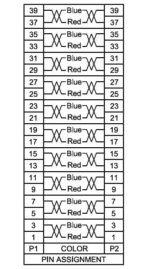
Design example: 10 LVDS pairs schematic.
Summary
It is important to carefully plan the prototyping and production phase of your LVDS cable. Incorporating an LVDS cable into your design is an excellent way to provide high-speed data transfer rates within a relatively small cable cross section. Complex shielding schemes can be developed to make certain that the internal pairs of the cable do not negatively impact one another.
If you are stuck on what to do for your prototype LVDS cable, take two individual wires and load them into the chuck of your hand drill. Twist and spin away until the entire length is twisted thoroughly. These LVDS legs can support development and integration testing and are quite easy to fabricate. Like any project where custom electronics are involved, early engagement with a full-service manufacturer like Epec is critical for the success of the program.
Key Takeaways
- LVDS Requires Dedicated Twisted Pairs: Low-voltage differential signals must use individually twisted conductor pairs within the cable bundle. This reduces signal interference and supports higher data transmission quality.
- Twist Density Affects Performance: Increasing the number of twists per inch improves data transmission properties. Standard applications may use ~2 twists per inch, while high-speed data (1.5–2.5 Gbit/s) may require up to 5 twists per inch.
- Shielding Enhances Signal Integrity: For applications sensitive to electromagnetic interference (EMI), individually shielded twisted pairs with foil layers and drain wires can help maintain clean, reliable signals.
- Combining Power and Data is Common: Multi-conductor cables often mix LVDS pairs with power conductors in a single cross-section. This design is frequently used in USB, CAN, balanced audio, and other mixed-signal applications.
- Customization May Be Necessary for Complex Projects: Off-the-shelf options are available, but custom cable extrusions can integrate multiple LVDS pairs and various wire sizes. Early prototyping and testing are crucial for ensuring performance before high-volume production.


