


As printed circuit boards (PCBs) progressed, requiring their functions to be more and more complex and diverse, the number of layers increased from 1-2 layers, up to 4-30 layers, with 4-12-layer boards being more typical.
The stack-up (build), includes copper cores and prepregs to hold the layers together. These are the dielectrics. The simple definition of “dielectric” is an insulating material that allows electric fields to pass through it. It is not an insulator that stops electrical fields. Dielectrics can actually store charges, where insulators only cannot.

Why Specify Dielectrics?
First, a capacitor, which stores electrical energy, can do so without a dielectric. But, when a dielectric is added in, and even though the capacitor’s ability to store power remains the same, the dielectric lowers the electronic field and the voltage of the capacitor. This makes the capacitor more efficient in storing energy.
Dielectrics cause the charged electrons that enter it when voltage is applied; to polarize, negative electrons become positive, curtailing just how far into the dielectric they can travel. Also, the amount of this polarization of electrons directly influences the amount of energy that is stored. Specifying dielectrics then has a direct impact on what your PCB is designed to do and how much power will be sent through it.
Choice of Dielectrics
Dielectrics have several characteristic values given to them to differentiate what they can handle for your project.
- Peel strength: The amount of force required to peel the copper off the material it is bonded to.
- Volume resistivity: The material’s resistance to electrical current leakage.
- Surface resistivity: The resistance to leakage of current along the material’s surface.
- Moisture absorption: The amount of moisture or water the material absorbs if immersed for a period of time.
- Dielectric breakdown: When an amount of current exceeds the material’s breakdown voltage and the material becomes conductive.
- Permittivity: This is the amount the material can store energy in an electric field.
- Loss tangent: Calculation for the loss of energy going into the dielectric material.
- Flexural strength: The maximum bending the material can handle before it breaks.
- Arc resistance: The amount of time under low voltage that it takes to make the material conductive.
- Thermal stress: Stress that occurs due to differences in temperatures.
- Electric strength: Maximum electric field the material can withstand without losing its insulation properties.
- Flammability: The material stops burning after 10 seconds.
- Halogen content: Elements used in the production of the material.
- Glass transition temperature: The temperature at which the material changes into a soft (not melted) state.
- Decomposition temperature: This is the temperature it takes to break the material into the separate elements it is made of.
- CTE Z-axis: This is the coefficient of thermal expansion (temperature at which the heated material will expand in the Z direction).
- Time to delamination: The time it takes for the material under temperature to fall apart into its separate elements.
- CTI: This is the comparative tracking index value. This is a measure of the electrical breakdown characteristics of the material. (The larger the CTI number for an insulator the better).
So, all these items on the material spec sheet can be referenced to choose the correct material dielectric for the electrical PCB design.
Also, in multilayer PCBs, prepregs are used. The above FR4 example is used for a core, which has copper laminated onto it, and the material is also already hardened and cured. Prepregs do not have copper and are not cured, so that the resin inside can melt and be used as an adhesive to hold the multilayer together. So, for stack-ups, cores and prepregs can be chosen to reach the desired overall board thickness and spacing between layers.
Defining PCB Stack-ups
If you look at the table below, the first parameter lists the resin content, which refers to how much of the prepreg will melt into an adhesive. Then the thickness is shown, which matters, of course, for the final board thickness.
Prepreg Data
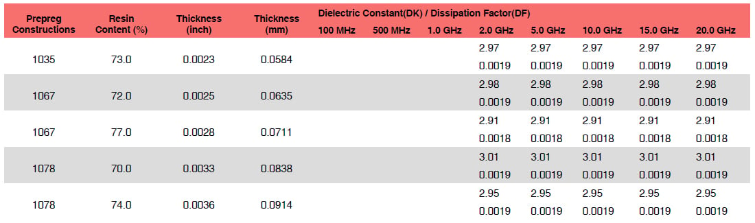
Example of common prepregs used in PCB manufacturing.
Then, the dielectric constants and dissipation factors are shown. The dielectric constant, in simple terms, is how much energy will permeate out of the capacitor, thereby affecting the amount of energy stored. This number reflects how much polarization occurs. So, the higher the number, the better for stabilizing charges. The dissipation factor is the measurement of the rate of energy loss.
In the table, one of the 1078 prepregs has the best dielectric constant and average dissipation factor. This is a simple view without getting heavy into physics and electrical engineering. For building a bare multilayer PCB, we as a manufacturer just need to know a few things: overall board thickness, finished copper weights, and core material required. The prepregs can be adjusted to create a balanced construction or offset to accommodate controlled impedance requirements.
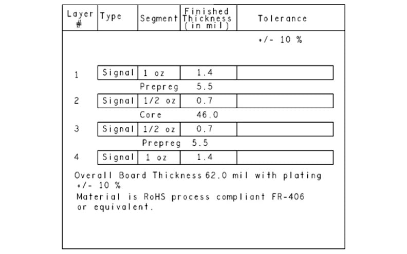
Example of a 4-layer PCB stack-up.
This stack-up illustration above includes the finished copper weights. It shows the prepreg thickness, the core thickness, and the final overall thickness. This type of stack-up allows the PCB manufacturer to choose the prepregs and adjust for a good balanced build. A stack-up can be very detailed, although this can limit manufacturers and add cost.
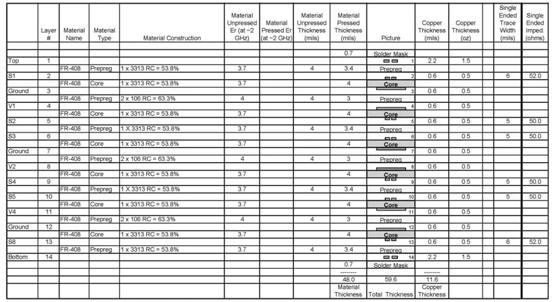
Example of a 14-layer PCB stack-up.
Circuit board stack-ups, like the one shown above, are more complex. Usually however, when a stack-up like this is presented to a manufacturer, changes will be requested, especially when the manufacturer calculates for the impedances.
For a PCB manufacturer, the simpler or more generic the stack-up, the better. Only a few items of information are usually needed:
- Core material required
- Finished copper weights required
- Overall board thickness required
- It really helps if equivalent materials are allowed
Flex & Rigid-Flex PCB Builds
Flex and rigid-flex circuit boards have some differences in the stack-ups. They require what is called no flow prepregs, which are almost the same, just that the resin is more cured so that it does not make a mess at the rigid to flex transition areas. Other than that, the rigid areas are built the same other than the polyimide adhesiveless cores are added in.
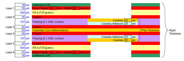
Example of a rigid-flex PCB stack-up.
In the above image, you can see the mixture of FR4, prepregs, and the polyimide cores for the flex layers. Again, we need the final required thickness, final copper weights, and the core material requirement. In this case, that is FR4 Tg170. Additionally, we need the thickness and copper weights for the flex area for a correct build.

Summary
PCB designers create a layout of a PCB to achieve a reliable circuit board that does all the functions desired. Thus, it becomes very important for the PCB manufacturer to receive the pertinent information. The PCB stack-up becomes a vital part of that information besides the fabrication notes and the drill chart. The stack-up reveals the desired copper weights to handle the current and impedance requirements. Also, the desired spacing between layers and overall board thickness will come out correct. Reliable communication between PCB designers and PCB manufacturers results in a great quality and successful printed circuit board.
Key Takeaways
- Role of Dielectrics in PCBs: Dielectrics are insulating materials used in PCB stack-ups to separate copper layers, store energy, and influence electrical performance. Specifying the correct dielectric directly impacts signal integrity, impedance, and power handling.
- Key Material Properties: Designers must evaluate properties like peel strength, resistivity, moisture absorption, dielectric breakdown, permittivity, loss tangent, CTE (coefficient of thermal expansion), and glass transition temperature when selecting dielectric materials.
- Prepreg vs Core Materials: Cores are copper-laminated, fully cured dielectric substrates, while prepregs are uncured resin sheets used to bond layers together. Prepreg selection allows manufacturers to fine-tune layer spacing, board thickness, and impedance requirements.
- Stack-up Simplicity vs Complexity: A simple stack-up (e.g., 4-layer) is easier and more cost-effective to manufacture, while complex builds (e.g., 14-layer) may require adjustments by the PCB manufacturer to meet impedance, copper weight, and thickness requirements.
- Rigid-Flex Design Considerations: Rigid-flex PCBs require no-flow prepregs to prevent resin overflow into flexible areas. Designers must specify copper weights and dielectric thicknesses for both rigid and flex sections to ensure proper performance and manufacturability.


