


There are a very wide variety of materials available to construct a flexible circuit. The materials range from different types of copper, copper thicknesses, core/coverlay and adhesive thicknesses, adhesive types, stiffener types and thicknesses, PSAs, shielding films, flexible soldermask colors, etc. Inadvertently specifying unique or non-standard materials can result in significant delivery delays as they may not be standard stock at either the manufacturer or the supplier.
All manufacturers maintain an in-house stock of the most commonly used materials that satisfy the needs of a high percentage of their customer’s requirements. The same applies to material suppliers.
Calling out for a non-standard stock material at the manufacturer level may add weeks to the delivery of the parts as they wait for material delivery. Calling out for a material that also happens to not be standard stock at the material supplier may add months to the delivery schedule as they wait for it to be manufactured.
In this blog, we will review some of the more common material requirements that we encounter that can create delivery delays in a flexible circuit design.

Thicker Flex Cores
The most common material callout we encounter that can create a delivery delay is the flex core thickness. In most cases, the customer is calling out for a thicker than “normal” flex core. This is usually tied in with a controlled impedance requirement. While the chosen thicker core, combined with the line widths/spacing used, will achieve the impedance values the negative impacts are delivery delays due to a non-stocked material, a thicker, less-flexible design and higher part cost. In most applications, a thinner core combined with thinner lines widths spacing and copper thickness can be applied to meet the impedance requirements.
Flexibility and the ability to meet a tight bend radius requires the use of thinner materials. As such, the most common core thickness ranges from 0.0005” to 0.003” with 0.001” the most used. Some material suppliers list thicker cores but they are not necessary all readily available due to limited demand and requires a special order.
If a thicker core is indeed necessary, there may be options of laminating multiple thinner layers together to avoid any delays.
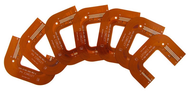
Example of flex circuits with a thicker construction.
Copper Weight & Type
Copper weight is a critical element in a flex circuit design. Driven again by bend requirements a thinner copper is often necessary. The most common copper thicknesses range from 1/3 OZ to 1 OZ with 1/2 OZ being the most common. There are also two types of copper available: rolled annealed and electro deposited. Rolled annealed is preferred for very tight bend requirements and electro deposited is less expensive for more cost-sensitive applications with relaxed bend requirements.
Flex circuit designs that have higher current carrying requirements, and as such need thicker copper can create delivery delays. While 2 OZ copper is somewhat common, it will be typically limited to a 0.001” flex core to maintain as high a degree of flexibility as possible; 3 OZ copper and higher may be available as a special order from some supplies but with a large delivery delay. In most cases, a manufacturer will “make” the material by laminating bare copper to a layer of polyimide, but again this incurs cost and delivery delay.
PSA Requirements
Many flex designs utilize a PSA (pressure sensitive adhesive or double-sided tape) to either mount the flex within the assembly, attached the flex to a heat sink for thermal dissipation or to electrically connect the flex to another part of the assembly. The challenge comes from the fact there are so many types of PSAs available that stocking even a small percentage is a large expense. PSAs tend to be readily available from the suppliers but the issue at times is the size format. Flex circuit board suppliers tend to work with wider roll widths and the manufacturing processes are not compatible with a 1-inch wide roll as an example. The most commonly used PSAs are 3M’s 467 and 9077. The 9077 is used on designs that have an automated assembly requirement as it is reflow temp rated.
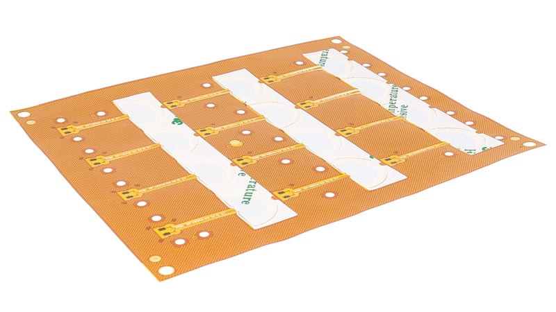
Example of a flex circuit with pressure sensitive adhesive.
Flex Circuit Stiffener Materials
Unique stiffener requirements can lead to delivery delays. Standard stiffener materials are FR4, polyimide, some stainless steels, and some aluminums. While a very wide range of FR4 and polyimide stiffener thicknesses are part of standard stock the same is not true for stainless steel and aluminum stiffeners due to their limited demand in the industry. Specific stainless steel and aluminum alloys will most likely be special order materials. In addition, metal stiffener fabrication may need to be outsourced leading to both a material supply delay and an outsource delay.
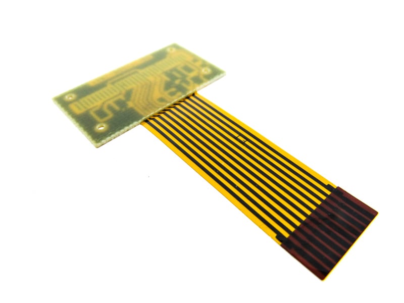
Flex circuit with FR4 and polyimide stiffeners.
Coverlay & Flexible Soldermask
Coverlays, as with flex cores, are available in a variety if thicknesses but some have very limited demand. By far the most common thickness is 0.001 with 0.0005” used for designs with very tight bend radiuses or a dynamic bend application. Some suppliers list up to a 0.003” coverlay for special applications but will most likely not be standard stock for the manufacturer. Same as the alternative thicker flex core solution it may be possible to laminate multiple coverlay layers to meet a specific requirement.
Coverlays are also available in black or white in addition to the natural polyimide color, but the thickness will be limited to 0.001” in most cases.
Some designs may require the use of a flexible soldermask in place of or in addition to a coverlay. The main delivery challenge may be the color available. Green will be a standard stock, and potentially yellow, but other color availability will be limited again due to very limited demand.
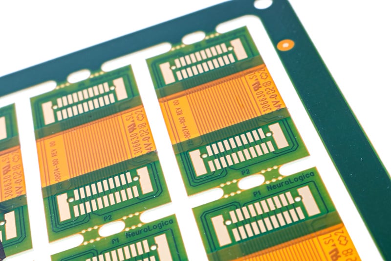
Example of a flex circuit with coverlay and flexible soldermask.
Summary
As we covered in this blog, the wide variety of available materials can negatively impact the delivery if unique materials with limited demand in the industry are selected. We encourage our customers to allow Epec to support their design process by reviewing the material requirements to ensure timely deliveries, that design requirements are met, and the design is cost-effective.
Key Takeaways
- Non-standard materials add delays: Unique or rarely used cores, adhesives, or films may not be stocked, adding weeks or even months to lead times.
- Flex core thickness impacts timing and flexibility: Thicker cores often require special orders; using thinner cores with adjusted copper and trace widths can meet impedance needs while avoiding delays.
- Copper weight affects both bend performance and availability: Common thicknesses (⅓ oz to 1 oz) are stocked, but heavier copper like 3 oz often requires custom lamination, extending delivery time.
- PSA and stiffener choices can slow production: While common 3M PSAs and FR4/polyimide stiffeners are standard, exotic PSAs or metal stiffeners like stainless steel typically require special orders and outsourcing.
- Coverlay and soldermask options are limited: Standard 0.001” polyimide coverlay and green soldermask are readily available, but thicker coverlays or non-standard colors usually introduce delays.


