


From a printed circuit board (PCB) manufacturing supplier’s point of view, often we are consulted about design and layout at the concept phase. Over the past many years, we have seen an increase in customers asking to assist with design, layout, and modifications to the circuit board. From this repeat request, we developed an engineering team to make it happen.
While the number of PCB design and layout requests has been increasing over the past few years, we feel it would help our customers to create content to help them.
In this blog post, we will discuss why we want our hands on your PCB design at the beginning of the process and how it can benefit you as our customer.

PCB Design Software
PCB design software is not something we as a manufacturer consider to be important to us; it is the output format from the design software that matters. As Epec has increased PCB design and layout support over the past several years, we would like to weigh in our thoughts to help our teams and also our customers.
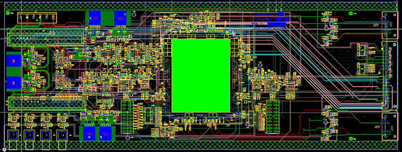
Example of a high-speed PCB Design.
For software, our preference is Eagle PCB schematic format, however, we can also support Design Spark, PADS/OrCAD/Cadence, Allegro, Altium, Protel, and, in some cases PDF or image files are fine too. A clear format of any of these is fine for an initial quotation for layout. We do not provide support for initial design of the PCB at the electrical engineering level in most cases unless the project is large enough of an opportunity and can include other assembly and final product opportunities.
Schematic Details
For Epec to support the layout and routing of the PCB, we first need some items. The schematic should include all the pertinent layout notes for all the nets items that have special requirements such as controlled impedance, differential pairs, high current/high voltage, minimum/maximum spacing, sensitive analog circuits, star grounds, high frequency, or other unusual considerations. Any special keep-out areas should also be noted for layout.
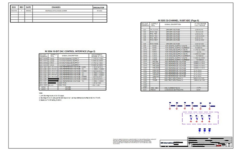
A good BOM will include the manufacturer's part number, the quantity needed, and details of the part.
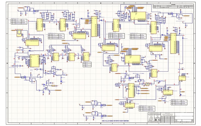
The schematic drawing details are critical to layout and accuracy of the functionality of the PCB and its final product.
Bill of Materials
The Bill of Materials (BOM) is another critical item to provide to the design and layout team. A list of components by manufacturer part number or source number, the quantity of each part, and if any cross-reference is allowed. Noting any long lead time parts is recommended if you are aware of any. If there are data sheets available for non-standard parts or specialized components or hardware, including these simplifies the process of researching for them.
PCB Attributes
The printed circuit board details are just as important as the previously mentioned. Special certifications to be met should be clearly noted as part of the initial quote. Supplying a 1:1 outline or overall X, Y dimension gives the engineering team a perimeter to stay within. Also critical to layout is the total overall thickness that the part must meet as a maximum.
If there is an expected layer count to be met, any special keep-out areas or critical placement of components. Noting the mounting holes needed or areas to be cut out as well on the outline is a perfect way to alert the design team. Special marking requirements such as part numbers and revisions or serialization should be noted for visibility after assembly is completed. We always assume the part will be RoHS compliant due to the way of the world so let us know if it is not.
Deliverables
Expectations and deliverables are critical to convey during the quote phase. Set a realistic timeline to be met for the layout to be completed and what the deliverable package should be. Our standard package includes complete Gerber files in RS274X format, English units (inches), positive layers; drill tool and drill job files, a schematic in pdf format; a construction drawing/readme file in pdf format; a bill of materials in comma separated value text file; and a pick and place file for the top and bottom layers (instance, x, y, rotation, value, package).
Summary
Customers have a lot of options when it comes to PCB manufacturing, but all do not have the supply chain or options that Epec does. We do our best to help you on the ground floor during concept rather than at PCB quote where manufacturing can be a challenge and costly. Consult your PCB supplier for assistance, use the engineering resources, like our free DFM service and get a better product faster.
Key Takeaways
- Early Manufacturer Involvement Saves Time and Cost: Involving your PCB manufacturer at the concept phase can prevent costly design errors and reduce production delays. Epec encourages early collaboration to ensure manufacturability from the start.
- Schematic and BOM Clarity Are Crucial: A detailed schematic with layout notes and a comprehensive bill of materials (BOM) helps streamline the layout process. Highlight special requirements like impedance control, analog sensitivity, or unusual components early on.
- Design Software Format Is Flexible: Epec supports multiple PCB design software outputs, including Eagle, Altium, OrCAD, Allegro, and others. What matters most is receiving clean, accurate output formats, not which software was used.
- Communicate All PCB Attributes Upfront: Providing complete board specifications, such as layer count, board thickness, certifications, and mechanical outlines, ensures a smoother design process and avoids rework later.
- Define Expectations and Deliverables at the Quote Stage: Set realistic timelines and clearly define what file outputs you expect. Epec’s standard deliverables include Gerbers, BOM, pick-and-place files, PDFs, and more, everything needed for seamless manufacturing and assembly.


