


It is sometimes necessary to have some, or all, of your PCB layout projects done by an outside source. If you’ve never done a layout before, or if you don’t have the tools or experience to take on more complex projects, it is often better to have a professional complete the work.
Perhaps your company does have its own talented designers and layout personnel on staff, but pressures such as a heavy workload or an impending deadline may leave you needing to find an auxiliary source to cover a shortfall of in-house resources.
You may also find yourself with a legacy design that had been realized in a CAD format you no longer use, which you want to update without creating a whole new project in your present CAD software.
These are just a few common situations for which enlisting the help of an outside PCB layout service can be an excellent solution. The key to success will be how clearly and completely you are able to communicate your requirements, so that the quoting and project execution will proceed smoothly and end in success.
Define Your Requirements
The first thing you should explain is what you’re trying to achieve with your project. It is best to furnish a combination of a brief written outline explaining the PCBs function, with a listing of design documentation you will be able to supply. The time and resources required to complete a PCB layout will vary significantly depending upon how well you define the project’s scope, and how much specific information you are able to furnish. For the best pricing and delivery, more information is always better than less.

Essential Items for a PCB Quote
The bare minimum most PCB layout services will want to receive is a schematic, a bill of materials (BOM), and a placement drawing.
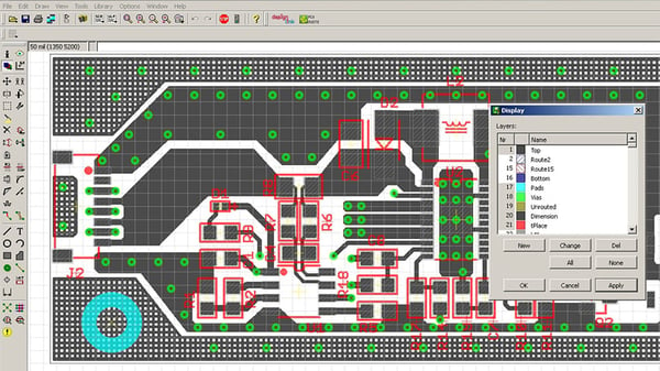
A PCB viewed in native CAD program at a point near completion.
1. Schematic
The schematic can be anything from a handwritten item, scanned to either JPG or PDF format, to a fully-developed CAD schematic file. If you send a scan, be sure that the resolution is high enough that it will be legible both on-screen and printed. If you send a CAD schematic, mention the CAD format from which it originated, including the software release level if known. This information will inform the layout service about the relative ease or difficulty involved in importing the data files into a different system if theirs is not the same as yours. CAD programs are very costly. Most services use only one or two types, so understanding the format can be important.
2. Bill of Materials
The most common BOM format is the Excel spreadsheet, although other file types are acceptable so long as they are complete. A BOM should list each component which will be used in the assembly, including the manufacturer, the part number, and the quantity for each type. Sometimes a BOM is embedded into the schematic, but in such cases only the component type and value may be listed. This missing detail compels the layout service to ask for more specific information. You may receive a question asking you to clarify such whether the components are to be through-hole or SMT types, and if they are SMT, then what types you want to use (0402 vs. 0603, etc.) These details will affect the amount of surface area required for placement which, in turn, will drive layer count.
3. Placement Drawing
The third item you should include is a basic dimensional view, showing the X-Y dimensions of the PCB. It should also show the locations of components such as connectors or large processors which will need to be mounted in specific areas in order to meet form, fit, or function requirements. This is often referred to as a “key placement” document. The layout engineer will use this in conjunction with the component type specifics from the BOM, to help further understand how the available PCB surface area will be allocated. The placement document can show just the basic outlines of the components, or it can be fully-dimensioned, with component locations, tooling holes, and keep-out zones defined.
Additional Details to Communicate When Possible
Beyond these first three must-have items, you will want to list any critical or otherwise non-standard requirements whenever possible. These could include electrical performance specs such as high voltage, high current, high frequency, or impedance control. They could also include mechanical items such as maximum PCB height, cutout locations, maximum layer count, or a need for gold plug-in fingers to fit an external connector.
If you will need agency certification or firmware programming, these will affect the cost of the project, so include details explaining which party will be responsible for completing these steps – either you, or the layout contractor. Firmware programming is sometimes subcontracted by the layout service to an outside source, who will also need to review the requirements to establish time and cost.
Remember to state whether your board will be subject to export control restrictions such as ITAR. Similarly, if the PCB will be used by the military, then that information needs to be on your RFQ as well. The reason is that there are more stringent specifications for some aspects of military work. There are also strict guidelines governing the transfer of intellectual property through secure channels only. It is your responsibility as the customer to inform your layout contractor at the beginning of the project to be sure that all file transfers and other communications are conducted through secure channels.
Having explained as much as you can about the circuit board design itself, you should wrap up by defining your project timeline and listing the deliverables you expect to receive when the layout is completed. Deliverables will always include a full set of Gerber files for every layer, plus a drill file and a basic fabrication drawing. If you also want to receive a set of native CAD files, 3-D model files, or the like, then you need to specify which formats you prefer, to be sure that the service you select can provide the appropriate files formatted the way you need them.
Regardless of the relative simplicity or complexity of your project, expect that it will usually take a couple of days before you will receive a quote. Layout quotes require time and attention. You should not be surprised if you first receive a list of additional questions that need to be answered before an accurate quote can be prepared. This is normal. Questions indicate that the contractor has reviewed and understood your information but wants to clear up a few loose ends in the interest of providing you with accurate pricing and a lead time they can stand behind.
If you receive a layout quotation back an hour after you send your RFQ, then one possibility is that you have a very simple project that was easy for the designer to review between other projects. The more likely possibility -- especially if you have a complex set of requirements -- is that you are dealing with somebody who does not have any other work in their queue, and who may not understand the scope of the project. Be cautious about any low-ball quote that comes back to you in record time. It may not be the bargain it appears to be.

Summary
In all circumstances, your PCB layout project will go more smoothly the more information you are able to provide at the time of your request for quotation. When you supply as many relevant details as possible, you ensure that the quote you receive will be accurate, and that the project will have its best chance of remaining on schedule. From the point at which the project actually begins, there should be few or no delays caused by the need to stop for another round of Q+A, and whatever questions do arise should prove to be minor. The last thing anybody wants is to find themselves backtracking to fix previous work on account of a major omission in the original scope of work. A complete set of requirements will minimize stoppages and will result in a functional design delivered on schedule.
You may refer to our Printed Circuit Board Layout Services PDF for a listing of information you should consider sending with your next PCB layout quote request.
Key Takeaways
- Clear requirements ensure accurate quotes: A written outline of the PCB’s function and available documentation helps layout services understand scope and reduce back-and-forth delays.
- Three essentials for any layout quote: A schematic, a bill of materials (BOM), and a placement drawing are the minimum items needed for an accurate and efficient layout quotation.
- More detail improves pricing and delivery: Supplying component specifics, form/fit requirements, and non-standard conditions (high voltage/current, impedance control, etc.) allows the contractor to prepare realistic costs and timelines.
- Include compliance and special requirements: Information such as ITAR restrictions, military use, agency certifications, or firmware programming responsibilities should be communicated up front to avoid surprises.
- Expect questions before a final quote: Reliable contractors may ask clarifying questions and take time to provide accurate pricing, while overly fast “low-ball” quotes can signal risk or lack of understanding.


