


Solid modeling is the process of constructing a 3D model through a series of additive and subtractive operations while always maintaining a calculable volume. Surface modeling is the process of constructing a 3D model through the process of defining each of the faces that are present in its geometry.
A conceptual way to think about these two types of modeling is solid modeling is a carpenter gluing and shaping pieces of wood to make a toy car, whereas surface modeling could be equated to a stained glass artist cutting out panels of glass and soldering them together at the seams to make a lampshade.
It helps to understand what a CAD file is to the computer, which, put briefly, is a collection of points located in 3D space relative to the origin and the information noting how faces are constructed between them. It can be helpful to imagine the computer playing a game of 3D Connect the Dots when it does the work to render and represent that model. Surface modeling is when you take direct control over that those positions and relationships. To the computer under the hood, all models are surface models. Solid modeling is a constructed framework for the drafter to speed up their ability to work. When creating a rectangular feature, it is easier to imagine putting a rectangle on a particular face rather than working out each of the 8 points and their location in 3D space and relation of the faces to said points. The reason one may turn to surface modeling is that certain geometry and features are unattainable through conventional solid modeling means. See our blog post on design principles and best practices for surface modeling for more information.
The conventional wisdom is that surface modeling is for curved bodies, and with solid modeling, this is partially true. An important note to understand is that both these processes can be used to achieve the same result. Also, surface and solid modeling do not exist in a binary and can be used in tandem to construct your desired geometry. Some examples of applications for surface models are an overmolded handgrip, the body of a car, injection molds for plastic and rubber parts, a propeller blade, or a boat hull. What these parts have in common is that they have multiple splined surfaces that interconnect.
Tools of the Trade
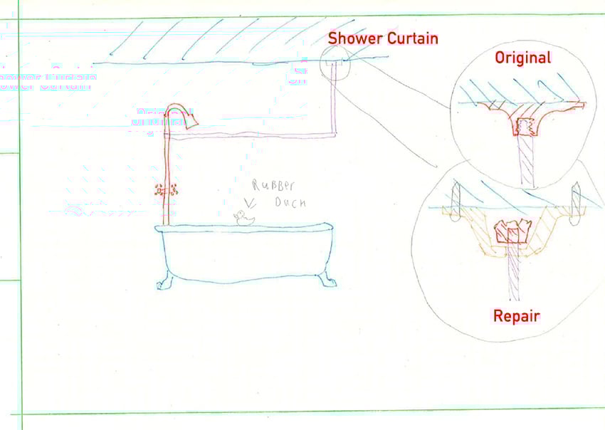
Hand-drawn diagram.
I started the CAD file as a simple revolve feature, to which I added a bolt hole pattern to with an extrude cut. At this point, the 3D model would have been perfectly functional. In the name of mating the houses aesthetically but secretly fun, the decision was made to add petals around its circumference. This was achieved by converting the solid model to a surface model, and then taking the spline face and offsetting it away for the original. The offset face was then trimmed to a petal profile. Pictured below is a brief synopsis of the CAD process.
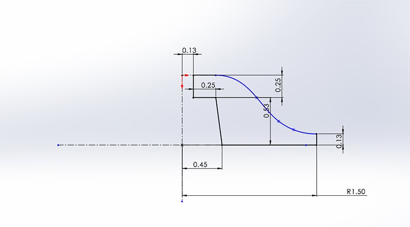
Revolve profile.
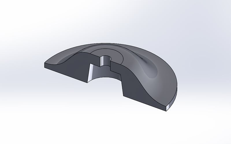
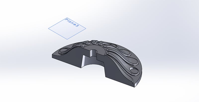
Part sectioned for clarity about what is happening in the model. Note the filled in cross section this indicates that it is a solid part.
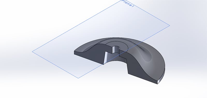
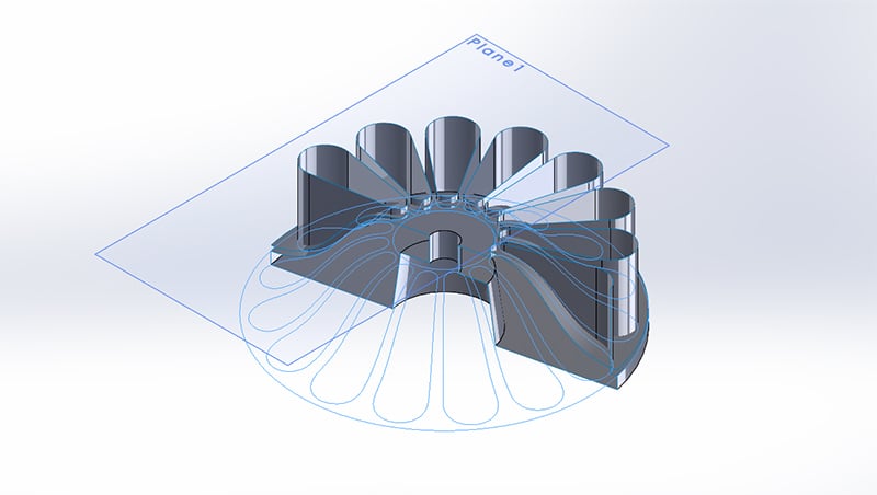
Construction plane made.
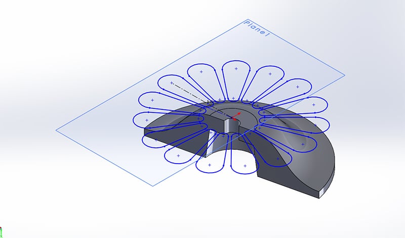
Petal profiles played out with the revolve feature.
Extrude profile tool from the surface tools section.
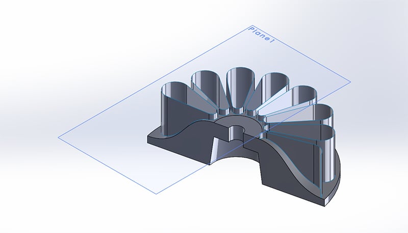
The domed solid part is converted into surfaces. Note how the cross section shows the interior of the part.
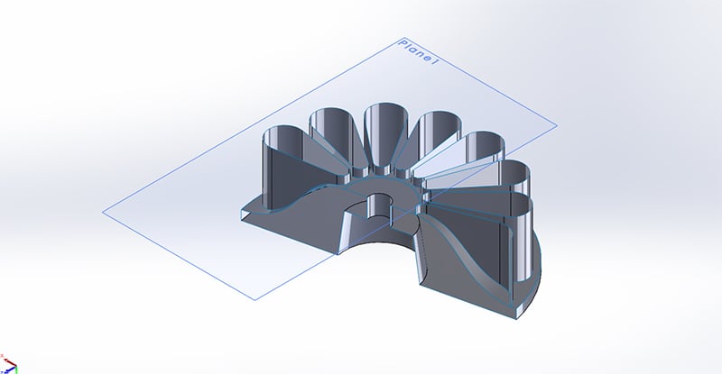
The domed faces then offset using the offset surface feature.
The faces at the center of the petals on the lower domed face are deleted.
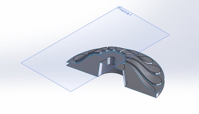
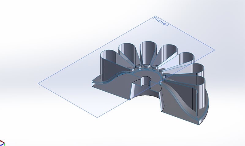
The side walls and surface between petals is trimmed away and knit together; unknit edges are highlighted by solid works in teal.
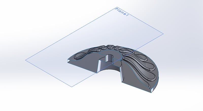
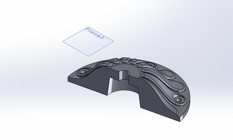
Fillet is added to the tops of all petals.
Part is knit back into a solid body.
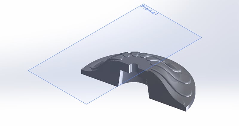
An additional construction plane in made to extrude cut a flat for mounting holes.
Through holes added with hole wizard.
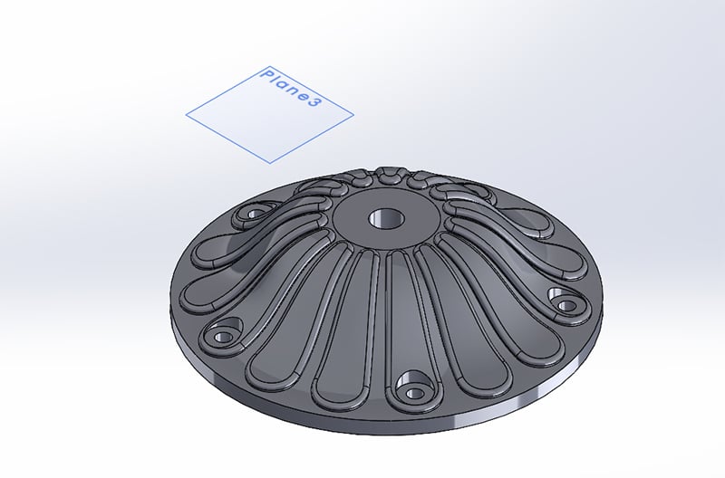
Finished part.
Summary
Basic surface modeling skills are a very good complement to any draftsman skill set. It can be a very effective tool to achieve nonstandard shapes, and most of all the tools surrounding it as a practice are variations on solid modeling tools. I encourage anyone who has not given it a try to take a half-hour to make a part and figure out the fundamentals.
Key Takeaways
- Solid Modeling Focuses on Volume, Surface Modeling on Faces: Solid modeling constructs fully enclosed 3D shapes with calculable volume, while surface modeling creates models by defining individual faces without necessarily forming a solid object.
- Surface Modeling Offers Greater Flexibility for Complex Geometries: Surface modeling is ideal for designing parts with intricate curves and non-standard shapes, like propellers, car bodies, or overmolded grips, that are difficult or impossible to achieve with basic solid modeling.
- Both Methods Use Similar Core Tools with Some Variations: While both modeling types use tools like extrude, revolve, sweep, and loft, surface modeling adds unique operations like boundary surface, offset surface, trim/extend surface, and knit surface to manage complex face construction.
- Combining Both Methods Yield Maximum Design Control: Solid and surface modeling are not mutually exclusive; hybrid approaches are often used to create functional parts with custom surface features, offering the speed of solids and the precision of surfaces.
- Surface Modeling Requires Care to Maintain Model Integrity: Unlike solid models, surface models can fail if faces are left unsealed. Infinitely thin or unknit surfaces result in incomplete geometry that can’t be converted into solid bodies or used reliably for manufacturing.


