The two main categories of 3D modeling can be defined as solid modeling and surface modeling. Solid modeling consists of extruding and cutting away from solid geometric volumes. This is great for subtractive and additive manufacturing methods such as milling and 3D printing.
Conversely, surface modeling involves the manipulation of thin sheets in 3-dimensional space. This is primarily used for parts that are being manufactured from sheet material such as metal stamping, vacuum forming, and bending. Surface modeling can also be applied to solid models that require a surface with complex geometry that would be much harder to model with solid modeling tools.
In this post, we will explain some design considerations and best practices for engineers who are getting started in surface modeling.

The Part vs. The Trim
When you first start out in surface modeling the best way to visualize the construction of the model is by breaking it up into two separate components. The first component of the model is the part itself. The difference between solid modeling and surface modeling is that with solid modeling you are adding chunks of material here and subtracting chunks of material there, but with surfacing you are combining multiple planes of material to achieve the desired end profile. Envision the part as this combination of planes that will extend far beyond the boundary of your finished design.
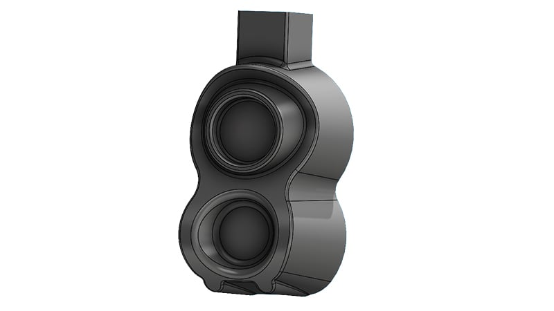
The part surface pre-trim.
The second component of a surface model is the trim surface. Envision this as a cookie cutter that gives you the final perimeter of the part. The trim surface is also constructed of planes that are combined and then intersect with the part surface. During manufacturing, this will closely resemble what is actually occurring during stamping. The stamping die will first consist of shapes that form the profile of the part with extra material around the perimeter, and then it is followed by a trim die that cuts out the finished shape. It is best practice to design the part first and then the trim afterward.
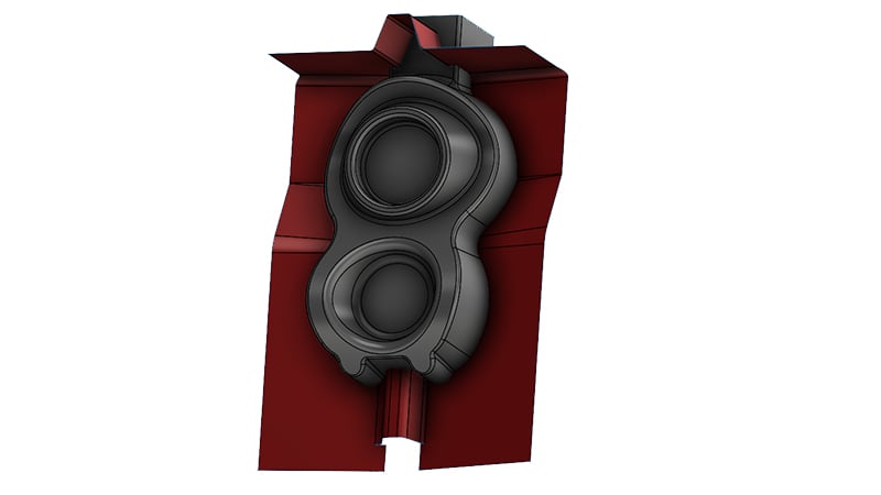
The red trim surface intersecting the part geometry.
Design Principles and Tips
When surface modeling, there are several design practices to keep in mind.
Be Mindful of Reference Planes
Many of the complex surfaces that can be created during surfacing are achieved using variable and other compound fillets. It is important to remember to construct independent references for these fillets instead of selecting arbitrary points. This creates a more stable fillet that is less likely to fail if the geometry is ever altered later. The same can be said for the surfaces being combined with each other. Providing reference planes that are fully defined gives the designer more flexibility when making changes to the part.
Keep Track of Your Thickening Direction
When modeling with surfaces it is sometimes easy to forget that the end part in the real world will have a nominal thickness. For simulation purposes, most surface-modeled parts are given a thickness at the end. When filleting flanges and other components with tight radii, keep in mind which direction you are going to thicken the part so that you do not create bends in the material that will be too tight to form in the real world. A good tip is to always model the outermost facing surface when viewed from the most common orientation, then you always will be thickening to part inwards.
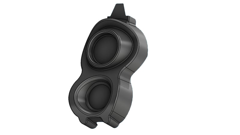
The final trimmed part.
Give Yourself Plenty of Space
When creating planes for both the part and the trim, give yourself extra material to work with by making the planes larger than you think you need. This will allow it to intersect with future planes more easily and give you more freedom to move planes around in future iterations without the hassle of planes no longer intersecting when you need them to.
Most Complex Profiles Can Be Created One Of Two Ways
The majority of compound curves and shapes are either created with fillets or from 3D scans. Using fillets gives the designer more control and the ability to alter shapes as a design progresses. 3D scans can take the work of a master sculptor or other source and implant those surfaces directly into a design. Scanned components are typically harder to manipulate but make truly complex surfaces achievable.
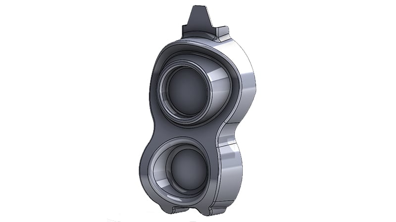
The part with thickness applied.
Summary
The last thing to remember when surface modeling is that you can combine it with solid modeling. Many injecting molded parts are designed with surface modeling to get the outer appearance and then solid modeling to add structure to the inside such as ribs and anchor points. Another way to combine the two is to use surfacing to create a complex profile that is then used as a trim surface on a solid model. This is a good way to create parts that have one decorative face to them. Keep these practices in mind as you are getting into surface modeling.
Key Takeaways
- Surface modeling is ideal for sheet-based manufacturing processes such as stamping, vacuum forming, and bending, while solid modeling suits additive and subtractive methods.
- Break models into part and trim surfaces so the part surface defines geometry, while the trim surface acts like a cookie cutter to finalize the profile.
- Use stable reference planes for fillets and surfaces, which prevents geometry failures when designs are modified later.
- Always plan thickening direction in the model outer surfaces first to avoid unmanufacturable bends when adding thickness.
- Most complex profiles come from fillets or 3D scans, with fillets offering design flexibility and scans enabling highly detailed, organic shapes.