


With advancements in rigid-flex PCB design technology, the use of laser-based systems in the manufacturing process are very common in the industry. Not having laser drilling and cutting available would place significant limitations on what could be accomplished in a design and what components could be used.
Like any other production tool, when combined with the specific materials and manufacturing methods required in a rigid-flex circuit board design, lasers have limitations that need to be understood and accounted for in a design.
In this blog, we will review the laser drilling and cutting process, where it is applied, and its capabilities/limitations when used in rigid-flex circuit board manufacturing.

Introduction to Laser Drilling
A laser source is used to provide the “drilling” or “cutting” process as opposed to a mechanical drill bit or router bit used in traditional manufacturing systems. Laser systems, however, do not actually cut the material. The high-energy application of the laser causes the material to vaporize or ablate. This may leave a slight charring on the edge of the feature due to the heat generated.
The laser source is configured to a specific wavelength that is most conducive to the material being cut and is focused to a specific diameter or kerf. The diameter is typically fixed and cannot be easily changed as you could in a mechanical drilling system by changing the size of the bit that is chucked into the rotating spindle.
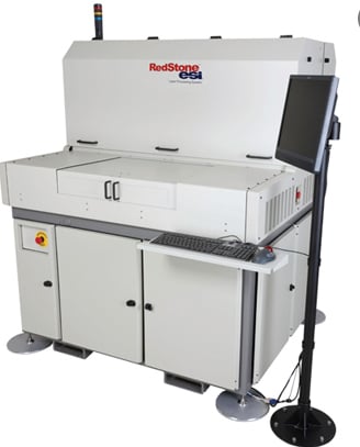
Laser systems have an overall similar configuration as mechanical systems. There is a working platen, where the parts are tooled/pinned into position, and then either the platen or the laser head is CNC-motion controlled in the X and Z axis allowing it to move with a very high degree of accuracy throughout the working area of the system. Systems are available in a wide variety of sizes which define the maximum part or production panel size that can be processed.
Laser drilling machines have a couple of significant advantages over mechanical drilling machines. The first being the smaller hole size they can achieve. Lasers can drill as small as 0.002” holes. Standard drilling systems are limited to a 0.006” hole size. Smaller drill bits are not available as they would be extremely fragile, wear out very quickly, and be extremely expensive. The second advantage is that most systems can optically align to the parts being drilled or cut. Fiducial targets are etched on the surface of the production panel in critical areas. This significantly improves the positional accuracy of the feature being lasered.
Laser systems have a couple of significant advantages over mechanical drilling systems.
Laser Drilled Hole and Slot Applications
Laser systems can be used to achieve a variety of different requirements in a rigid-flex PCB design.
Blind Vias
This is the most common application. Blind vias are required for high-density designs and BGA-style component packages. The small size of the via allows the via hole to be drilled within the SMT pad. The pad is then filled and plated over to provide a flat solderable pad for the component.
Through Vias
Commonly used for via holes in flex circuits or the flex areas of rigid-flex circuit designs. Again, the smaller hole size allows in turn for a smaller surrounding via pad and allows for a higher density circuit layout.
Part Outline Cutting
Reserved for flex areas only. Commonly used for prototype or small volume orders where the cost of punch and die tooling would be prohibitive. Flexible PCB materials do not cut cleanly when using mechanical routing. Ductile polyimide materials leave a ragged edge when routed. Laser cutting provides a clean sharp edge and is more cost-effective.
Intricate Part Outlines or Slots
Lasers, due to their very narrow cutting beam (kerf) allow for much smaller and intricately shaped slots or cutouts. Mechanical routing systems are limited by the diameter of the smallest available routing bit, typically 0.032”, and again leave an undesirable ragged edge. The positional accuracy and size tolerance of the feature is also significantly higher.
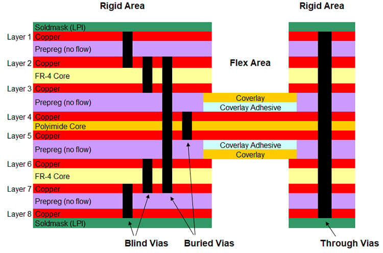
Example of an 8-layer rigid-flex PCB with blind and buried vias.
Laser Drilled Hole Size Limitations
While some laser systems can drill as small as a 0.002” hole, there are other factors that make this impractical and unmanufacturable. For blind via applications, the need to deposit plating within the barrel of the hole becomes a limiting factor. As the hole is blind, it does not allow for the plating solution to flow through the hole from both sides of the part. Because of this limited plating access, the max. recommended depth of a laser-drilled blind via is equal to the diameter of the hole. This is referred to as the aspect ratio (hole diameter vs. hole depth) which is a max. of 1:1. While a larger hole would allow for a greater depth, it would also consume more space in the design and for high-density BGAs would not fit within the available pad size. A common compromise is a 0.004” hole. This allows for up to a 0.004” depth, which is sufficient to reach the next later in the design stack up with the thickness of available rigid PCB materials. The laser itself is also focused to the 0.004” size which makes for efficient power application and allows the hole to be drilled in one position without having to circularly interpolate a larger hole size.
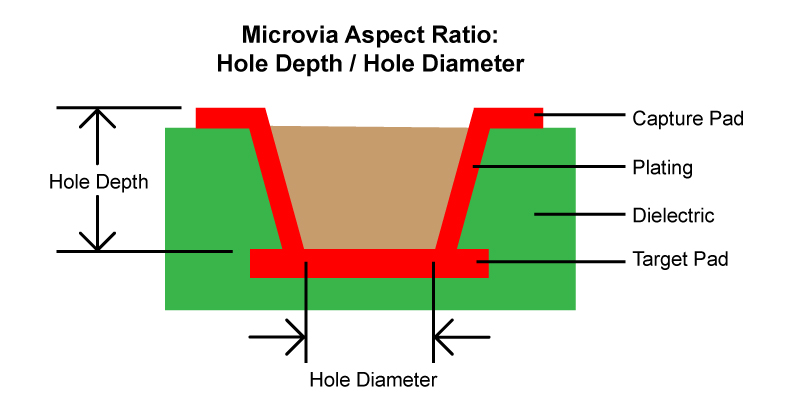
Microvia aspect ratio diagram.
Laser Positional Accuracy and Feature Size Tolerances
As mentioned earlier, laser systems have the ability to optically align to etched targets in the surface of the part. This capability improves the overall positional accuracy of the system by eliminating the inherent tolerances incurred using tooling pins only to locate the parts in the system. The significant added benefit is that it also allows the system to zero out a significant amount of the inherent dimensional changes in the part. Due to the materials used, the construction and the manufacturing methods used rigid-flex and flex circuit designs are not as dimensionally stable as a standard rigid PCB. Localized fiducials in critical areas allow for a significant amount of these added variables to be eliminated. There are however limitations to the extent of the positional accuracy that can be achieved. The quality/definition of the fiducials on the part, the optical recognition capability of the system, and the CNC positional accuracy of the system all have an impact. A general capability tolerance for both drilled holes and slot location is in the +/- 0.002” to 0.003” range.
Laser Drilling and Cutting Costs
Laser drilling is a more costly than mechanical drilling a cutting for several reasons. Most mechanical systems have multiple spindles/work areas that work in tandem allowing many more production panels to be processed simultaneously. Laser systems, due to the optical alignment capability, have only one work area, and this allows for one production panel to be processed at a time thereby limiting throughput. Mechanical systems are also faster at creating the individual holes.
Summary
Laser drilling systems have allowed rigid-flex and flexible circuit designs to achieve a higher level of technology than the previous mechanical drilling and routing operations. Smaller, more intricate features can be manufactured with a higher degree of precision. The significant negative element is that of cost. We recommend to our customers to have their designs reviewed using our free DFM service to ensure that the need for a laser system in manufacturing is optimized to allow for a cost-effective design.
Key Takeaways
- Laser Drilling Enables Smaller, High-Density Features: Laser systems can drill holes as small as 0.002", ideal for blind and microvias in dense designs, well beyond the 0.006" minimum of mechanical drills.
- Aspect Ratio Limits Blind Via Depth: For reliable plating, the maximum depth of a laser-drilled blind via should equal its diameter (1:1 aspect ratio), making 0.004" vias a practical standard for most stack-ups.
- Laser Systems Improve Accuracy with Optical Alignment: Optical fiducials allow for better positional accuracy (±0.002"–0.003") by compensating for material shifts in rigid-flex and flex layers during processing.
- Laser Cutting Excels at Intricate and Clean Flex Outlines: Lasers outperform mechanical routing for polyimide materials, providing cleaner edges and tighter tolerances on flex part outlines, slots, and small cutouts.
- Higher Cost and Slower Throughput Than Mechanical Method: Laser systems process one panel at a time and operate more slowly than mechanical drills, making them more expensive, best used only when necessary for critical design features.


