


Over the past several years LED based products have become increasingly popular, and as a result, so too have metal core printed circuit boards. The automobile and lighting sectors have both embraced the technology, as have consumers, given an LED based light can be about 5x cheaper to run than a comparable incandescent unit. Even compact fluorescents have slightly higher operating costs, and they cannot compete with the smallest LEDs when it comes to efficient use of space.
As a result of these and other factors, more and more devices now incorporate LEDs as a major design feature. There is, however, one aspect of LED operation that must always be accounted for in product designs: heat.

Metal Core Printed Circuit Board Advantages
In many ways, LEDs are like any other component that is mounted to a circuit board. If only a couple of LEDs are present such as green and red indicators for power-on power-off, then there is little reason to do anything unusual when laying out your PCB. However, there are lighting solutions that incorporate either rows or arrays of LEDs which remain turned on for long periods of time.
Keeping these devices cool so that they do not fail prematurely or create a safety hazard can become a major issue. Efficient cooling is also required to guarantee that light output remains consistent. Changing your PCB from a standard FR4 type to a metal core PCB (MCPCB), such as aluminum PCB, is an option worth considering.
Some advantages of a metal core PCB are that it uses special substrate materials which are specifically formulated to improve the reliability of designs that run at higher than normal temperatures. Instead of serving strictly as a mounting surface for the various components, the substrate actively draws heat from the locations of hot-running components through to the opposite layer of the board where it can dissipate efficiently and safely.
MCPCB has proven to be an excellent solution to the problem of how to cool a PCB which uses large numbers of LEDs. It is important to understand that there are differences between standard epoxy-glass boards and MCPCBs.
How do MCPCBs Differ from Standard Epoxy Glass Boards?
One important difference to understand between standard PCB and MCPCB is how the materials work together to produce the desired result. In a typical LED MCPCB, there is a single circuitry layer of copper foil which is bonded to a layer of thermally conductive dielectric material, which is itself bonded to a thicker layer of metal – typically either Aluminum 5052, Aluminum 6061, or Copper C1100.
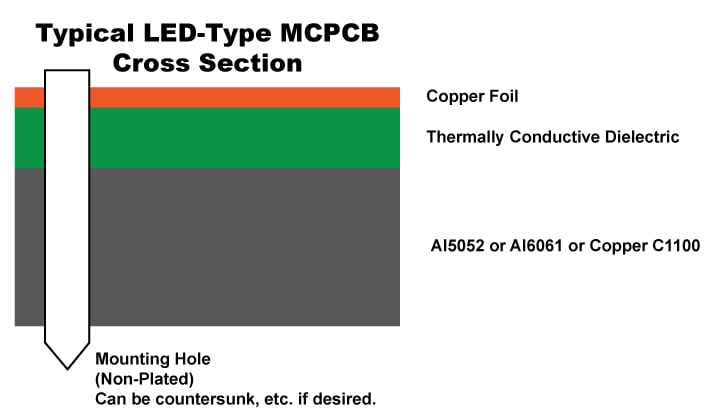
Typical LED-Type MCPCB Cross Section
The dielectric material’s thermal conductivity is measured in Watts per meter, Kelvin (W/mK.) A 2.0W rating is fairly common; such material is approximately 6x-7x as thermally conductive as FR4. The best practice is to keep the dielectric layer as thin as possible. Doing so creates the shortest possible path from the heat source to the metal backing plate which is many times more thermally conductive than the dielectric material. Most of the materials come in a very limited range of thicknesses anyway, usually between .003” and .006”. You won’t have all that much opportunity to specify something thicker that could diminish the effectiveness of the material at performing its thermal transfer function.
The metal backing plate used on the bottom side is the thickest element in the structure. It is available in several different thicknesses, but it is best to use one of the three most common (1.0mm, 1.5mm, and 3.2mm) because they are the easiest to purchase without delays. The metal layer adds rigidity, keeps the circuit flat, and adds enough thickness so that the MCPCB can use the same mounting hardware that would be used for any other standard thickness circuit board. The metal plate side of the board does not receive any surface finish or soldermask.
Metal Core PCB Surface Mounted Components
A key factor to incorporate into your MCPCB design is to not use any plated through holes and instead use only surface-mounted components. The reason for this is that the bottom of the layer structure is a thick piece of metal so a plated through hole (or a non-plated hole with a conductive component lead inserted into it) will result in a short.
Most LED PCBs built on multi-layered (2+) FR4 substrates must use a pattern of closely-spaced plated through vias under each component to transmit heat. Solder can migrate through these vias during assembly if these are not filled, resulting in a less than perfect solder joint.
With MCPCB, the work of vias is done by the materials themselves. The entire bottom side is composed of metal with a much more efficient thermal conductivity, so cooling is enhanced and vias are not necessary for thermal relief. The result is that most MCPCBs require minimal drilling – generally just a few large mounting holes.
The elimination of via drilling and the ability to stack multiple panels for simultaneous drilling of large holes enables the fabricator to move your boards quickly through what is often a bottleneck operation within a PCB facility. Then, after a short drill cycle, your 1-layer MCPCB bypasses the electroless copper deposition (or graphite) hole wall preparation step that would be required for PTH processing and proceeds straight to circuit imaging. From that point forward, your MCPCB follows more or less the same process steps that any standard FR4 design would follow.
MCPCB Manufacturer Considerations
There are some processing considerations for MCPCB manufacturing, but as long as you understand the way the materials work and you keep your design to a single-layer SMT-only type, then designing your board should not be much different from designing any other single-layer PCB. If you find that you cannot route your design to a single layer, note that other MCPCB configurations are possible, although they fall outside of the scope of this piece. These include:
- 2-layer, PTH boards with aluminum on the inside (which requires a costly pre-drill / fill with insulation / re-drill step to form plated through holes that won’t short.)
- 2-or-more layer boards built per standard PCB processes, but using thermal dielectric material in place of FR4, and a metal backing plate laminated to the bottom for thermal transfer.
MCPCBs can be an excellent solution when cooling of multiple LEDs is a design priority. They are becoming more and more common in a variety of lighting applications – for home, workplace, and vehicle. Although they are subject to certain design restrictions, the fabrication process is not radically different from most other PCBs and is in some ways simpler.
FR4 PCB vs. MCPCB Comparison
- Conductivity: FR4 has low thermal conductivity, typically around 0.3W, while MCPCB has higher thermal conductivity, ranging from 1.0W-4.0W, most commonly around 2.0W.
- Plated Through Holes: FR4 PCB typically uses plated through holes. Through hole components possible if required. In MCPCB, plated through holes are not available for 1-layer PCB. All components are surface-mounted.
- Thermal Relief: Thermal relief in FR4 PCB typically involves vias for heat transfer. Longer drill cycle, adds many processes. MCPCB materials provide their own thermal relief. Via drilling, deposition, and plating processes are eliminated.
- Solder Mask: FR4 PCB solder mask is typically dark colors (green, red, blue, black.) Usually applied top and bottom. MCPCB solder mask are almost exclusively white for LED boards. Applied to top only.
- Thickness: FR4 PCB has a wide range of thicknesses available using various material combinations and layer counts. MCPCB thickness variation is limited by available backing plate thickness and dielectric sheet thicknesses.
- Machining Process: FR4 PCB uses standard machining practices (drilling, routing, v-scoring, countersink, counterbore) while MCPCB uses the same machining as FR4, except that v-score must use diamond coated saw blades for the added strain from cutting into metal.
Summary
As LED-based applications continue to expand across consumer, automotive, and industrial markets, metal core printed circuit boards (MCPCBs) have become a vital solution for managing the heat generated by high-density LED arrays. Unlike standard FR4 PCBs, MCPCBs use thermally conductive dielectric materials bonded to metal backing plates, typically aluminum or copper, to enhance heat dissipation, improve reliability, and maintain consistent performance. Their design simplifies cooling by eliminating the need for thermal vias and supports efficient assembly with surface-mounted components.
While subject to certain design constraints, MCPCBs offer a practical and often more efficient alternative for high-power LED systems, making them a popular and increasingly essential choice for thermal-critical electronics.
PCB Manufacturing Explained: The V-Score & Jump Scoring Process
Key Takeaways
- Superior Thermal Management: Metal core PCBs (MCPCBs) are designed to efficiently dissipate heat, making them ideal for high-power LED applications where thermal buildup can affect performance and longevity.
- Material Structure Matters: MCPCBs typically feature a copper circuit layer bonded to a thermally conductive dielectric and a metal backing plate (usually aluminum or copper), allowing for rapid heat transfer away from critical components.
- Surface-Mount Design Only: One-layer MCPCBs do not support plated through holes due to the metal backing. All components must be surface mounted, simplifying the cooling path but limiting certain layout options.
- Simplified Manufacturing Process: MCPCBs often require fewer drilling steps and bypass some of the more complex plating processes used in traditional FR4 PCBs, which can streamline production and reduce bottlenecks.
- Ideal for LED Applications: With their enhanced thermal performance and efficient design, MCPCBs are widely used in LED-based systems for lighting, automotive, and consumer electronics, offering a cost-effective solution for managing heat in compact spaces.


