Computer-Aided Design (CAD) systems and software began replacing drawing boards during the 1980s. Today, there’s hardly an engineer anywhere who uses pencil and paper to produce engineering drawings. Everyone uses CAD, for the simple reason that it offers many advantages.
CAD packages take many forms. Most are intended for designing mechanical components, assemblies, and mechanisms, but there’s a subset that provides tools specifically for the electrical engineering community. Both mechanical and electrical CAD increase design engineer productivity and improve the quality of drawings as engineering documents. Perhaps of greater importance, they allow evaluation of more alternatives, which in turn improves the quality of the final engineered products.

Why CAD is Needed
CAD is a way of creating engineering drawings on a computer. This contrasts with the way they were produced for centuries previously, which was with pencil on paper. An engineering drawing communicates what a designer or design engineer wants to have made. It shows the shape, the dimensions with the limits of acceptable variation (the tolerances), the surface finishes required, and how parts should fit together. When drawn by hand, these would be copied by a process that produced white lines on a blue material, hence the term, “blueprint”.
CAD is performed on a computer using special software. This lets the designer place and link lines that represent edges and shapes. These can be connected so that if one line is moved, the linked lines move with it. CAD is often used to produce engineering drawings for manufacturing. These are typically 2-dimensional drawings with multiple views to show features that would be hidden if viewed from just a single orientation. CAD is also used to produce 3-dimensional drawings that give the viewer a better idea of how an object will look and relate to other objects.
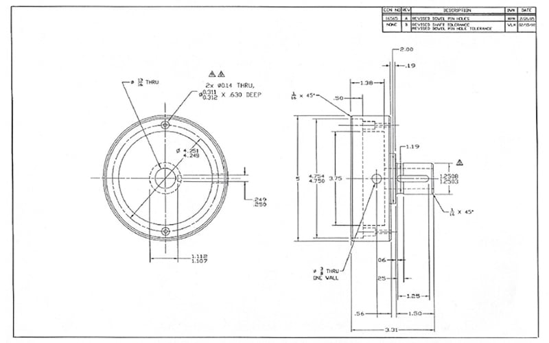
Manually generated CAD drawing.
How CAD Differs from Manual Drawing
Modern CAD software produces 3D, volumetric representations of physical objects. These can be manipulated and linked to create the geometric shapes needed. That speeds up the drawing process and reduces the risk of mistakes. The big difference though is that it allows the designer to view the objects being designed from any angle, see how they interact, and explore more options.
An engineering drawing created on a drawing board, no matter how skilled the designer, is just lined on paper. A CAD file is a digital representation of the part to be made. It can be reproduced and shared as many times as needed and used to create programs for Computer Numerical Control (CNC) machine tools. It may also be used to model and simulate how the part will perform in the real world; a process referred to as Computer-Aided Engineering (CAE).
In electronics, CAD can perform automated layout planning for printed circuit boards, increasing density while also helping avoid manufacturing and service problems caused by putting components or joints too close together.
Higher-end CAD programs can produce a bill-of-materials (BOM) that will go into an ERP system. Increasingly, CAD models form the basis of digital twins that provide virtual replicas of real-world devices and machines.
Distinguishing CAM From CAD
CNC machine tools follow programs that dictate a sequence of moves. These programs can be created manually but it’s faster and more efficient to use another piece of software that creates the cutter paths directly from the CAD file. This is the role of Computer-Aided Manufacturing (CAM) software.
CAM programs take the CAD information, plus information about the raw material type, shape, and size, and develop movement programs for the specific machine the job will go onto and the tools that will be used. If the job is a cylindrical part like a valve spool that will be turned and ground, the CAM program generates cutter paths for the lathe and grinder. If it’s a housing or enclosure that needs milling, CAM develops paths for the end or face mills.
A CAM program generates the machine tool part program quicker than is possible with manual programming. It will also find the fastest way to machine the part, because it incorporates algorithms that work out the most efficient cutter paths. That reduces cycle times compared to what’s achievable through manual programming.
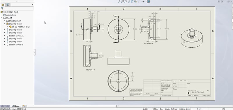
SolidWorks autogenerated 2D drawing.
Comparing CAD Products
A bewildering array of CAD programs are available, ranging from free downloads to highly sophisticated products with immense capabilities, (and substantial price tags.) The free programs provide basic 2D drafting capabilities, with a few offering 3D. These are satisfactory for the hobbyist who intends to have simple parts machined or 3D printed but lack the performance, capabilities, and support of the major commercial products.
At the professional level CAD is dominated by four companies: Autodesk, Siemens, PTC, and Dassault Systèmes. Each offers at least one product, divided into several tiers of capability to suit the needs of their users. Essentially, designing more complex products and wishing to perform more CAE analysis pushes the user towards the higher product tiers. All provide 2D and 3D design, but it’s at levels beyond this that differences emerge.
Autodesk has three well-known products:
- AutoCAD: The workhorse of 2D drafting, today with 3D capabilities.
- Inventor: A parametric, solid modeling tool.
- Fusion 360: A cut-down version of Inventor.
One notable feature of Autodesk products is that drawings produced with them use the .dwg file extension. This is readily imported into a wide range of viewers and CAM programs. Siemens is known for Solid Edge. This is similar to Inventor with extensive 2D and 3D solid modeling capabilities. PTC is the home of Pro-Engineer, usually abbreviated to Pro-E and now marketed by PTC as PTC Creo. This is a very capable CAD product with all the 2D and 3D solid modeling capabilities most engineers will need.
Dassault Systèmes is a French company that offers three CAD programs:
- CATIA: Suitable for designing the largest, most complex products, this includes 2D and 3D solid modeling plus CAM, CAE and even Product Lifecycle Management (PLM).
- SolidWorks: Available in 3 tiers and includes 2D, 3D CAM and electrical design.
- DraftSight: A scaled-back version of SolidWorks with a reduced set of capabilities.
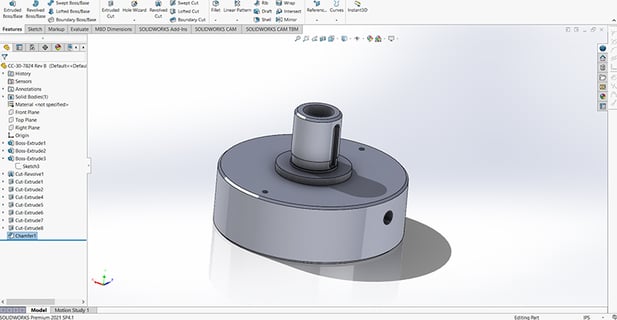
SolidWorks 3D part file.
How CAD Has Changed the Engineering Design Process
The big thing CAD has brought about is a single source of “truth” for product design documentation. Rather than different teams and functions working from different sets of drawings, they all have access to the same designs. Furthermore, they don’t have to redraw parts or assemblies to suit their specific needs. Instead, the same base data is used for BOM creation, PLM, CAE, and increasingly, digital twin creation. What this means, in short, is better products, designed, developed, and launched into manufacturing in less time.
Summary
In its early days, CAD was a tool for producing better drawings faster, but users quickly realized a host of additional benefits. It helped reduce mistakes and misunderstandings, aided communication and allowed evaluation of many more alternative designs. Today, CAD has expanded far beyond being a drawing tool. It captures the product definition in a way that is shared and used throughout the business. This saves time, increases productivity, facilitates the development of better products, and ultimately boosts business profitability.
Key Takeaways
- CAD Replaces Manual Drawing with Powerful Digital Tools: CAD systems provide dynamic drawing capabilities that adapt to changes, unlike static manual sketches. They allow engineers to visualize, modify, and simulate designs in both 2D and 3D environments.
- 3D Modeling Enhances Visualization and Reduces Errors: Engineers can rotate, inspect, and test assemblies virtually before manufacturing. This helps detect interferences and optimize component placement early in the design process.
- CAD Integrates Seamlessly with CAM and ERP Systems: CAD files feed directly into CAM tools for CNC programming and can generate BOMs for integration with enterprise resource planning systems, improving workflow efficiency.
- Flexible Software Options Serve Hobbyists to Industry Giants: While free or entry-level CAD software suits hobbyists, leading tools like SolidWorks, Inventor, and CATIA offer advanced features for parametric modeling, simulation, and lifecycle management.
- CAD Creates a Single Source of Truth Across Teams: Centralized CAD data eliminates version control issues, enhances collaboration between engineering, manufacturing, and quality teams, and enables innovations like digital twins.