


Flex and rigid-flex circuit boards are a combination of both electrical and mechanical requirements that allow for solutions to many tight packaging requirements. However, this combination is also the potential source of design challenges as some electrical requirements can have a negative impact on the mechanical bend capabilities of flex circuits. If not, correctly addressed the reliability of the finished design may be compromised.
In this blog, we’ll discuss the three most common electrical requirements that have a negative impact on the mechanical capabilities of a flex or rigid-flex circuit board and the potential solutions that can be applied to achieve a successful design.
Controlled Impedance
Controlled impedance designs, and their inherent requirement of thicker cores to achieve the required impedance values increase the flex thickness and negatively impacts both the flexibility and bend capabilities. The goal is to minimize the flex thickness as much as possible to allow for the greatest degree of bend capability and reliability.

In combination with the improved dielectric constant of polyimide, thinner copper weights and thinner trace widths/spacing than typically used in rigid PCB designs allow for a higher degree of flexibility and bend capability.
A common preferred configuration utilizes a 2-3 mil flex core, 0.5 oz copper and an approx. 0.004” line width. With minor adjustments, this will allow for the common 50-ohm single-ended and 90- to 120-ohm differential pair requirements.
An additional element is the configuration of the controlled impedance. The two most common being surface micro strip and stripline.
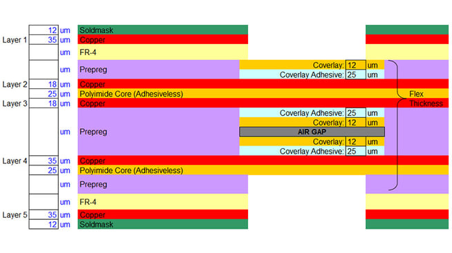
The surface micro strip allows for a thinner flexible PCB design (2 layers with a thinner core), while a stripline significantly increases the flex thickness (3 layers with 2 thicker cores). A stripline configuration is approximately 75% thicker than a surface microstrip. See images below.
Shielding requirements will also need to be evaluated to determine which configuration is needed.
To summarize, thinner controlled impedance line widths allow for thinner copper, thinner cores, and, in turn, improved flexibility and mechanical bend reliability.
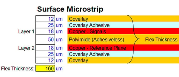
Example of a flexible PCB surface micro strip-controlled impedance stack-up.
.jpg?width=600&name=flexible-pcb-stripline-controlled-impedance-stack-up%20(1).jpg)
Example of a flexible PCB stripline controlled impedance stack-up.
Higher Current Carrying
Higher current carrying requirements pose a challenge due to the thicker copper needed. Increasing the copper thickness, however, has the greatest negative impact on flexibility and bend capability.
The preferred methodology is to utilize wider traces combined with thinner copper to achieve the current carrying capacity. This may require one or more of the following techniques:
- Increasing the width of the flex area to allow for wider traces.
- Using thinner copper combined with an additional layer to double up the current carrying circuits.
- Divorcing the current carrying layer from the signal layers in a rigid-flex design with an air-gap construction. (See image below with layer 4 dedicated to the higher current lines).
A careful review of the bend requirements is a necessary part of the design process to ensure the mechanical reliability of the finished parts. The bend capabilities of a flex circuit are determined by the design, construction, and materials only. The manufacturing process does not have an impact on flexibility.
Example of a rigid-flex PCB stack-up for higher current carrying requirements.
High Density/Interconnects
Designs with many interconnects, traversing the flex section(s), can lead to a higher layer count requirement which, in turn, constrains the bend capabilities. The goal is to either minimize the layer count and/or use a construction method that improves the flexibility.
Reducing the layer count by using a combination of the above is the optimum solution if the design allows. A 0.004” line and space with 0.5 oz copper may result in eliminating a flex layer, which will have the biggest positive impact on flexibility and bend capability/reliability.
If the flex layer count cannot be reduced, a rigid-flex design can use an air-gap construction where the flex layers are configured as independent sets or pairs from one another. This reduces the “I-Beam” effect and allows the flex layer pairs to bend independently from one another, which significantly improves the flexibility of the design.
This method can be applied to designs with 3 or more layers, impedance control, and or higher current carrying requirements. The copper weight and flex core thickness can vary between flex layer pairs as necessary.
We recommend a design review and bend capability input from your supplier to determine the optimum construction for high density designs.
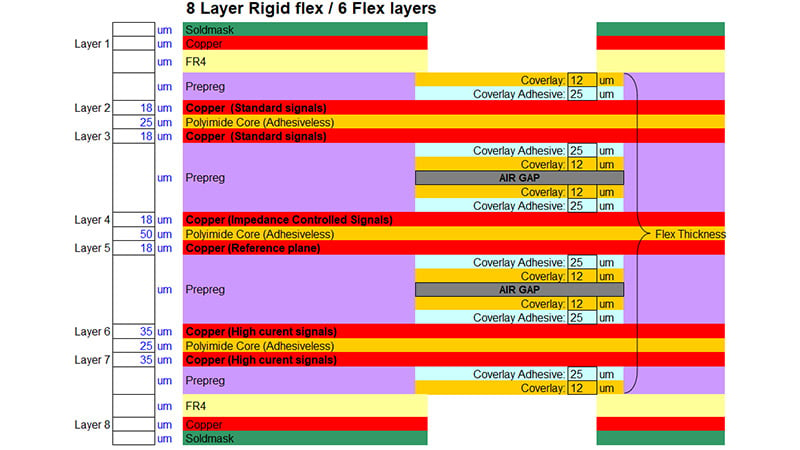
Example of an 8-layer rigid-flex PCB with a 6-layer flex stack-up for a high density / interconnect design.

Summary
A successful design meets both the electrical and, equally important, the mechanical requirements. The electrical provides the functionality and performance while the mechanical addresses the packaging requirements but also has the greatest impact on reliability. As discussed above, controlled impedance, higher current, and high circuit density can have a negative impact on the mechanical capabilities and reliability. There are many options available in materials and construction that will resolve this challenge and result in a successful and reliable design.
Key Takeaways
- Balancing Electrical and Mechanical Requirements Is Critical: Flex and rigid-flex circuits must meet both electrical performance and mechanical flexibility needs. Ignoring how electrical specs impact bend capability can compromise long-term reliability.
- Controlled Impedance Increases Flex Thickness: Thicker cores and copper weights required for controlled impedance reduce flexibility. Using thinner copper, narrower traces, and surface microstrip configurations can help maintain bend performance.
- Higher Current Requires Smarter Design, Not Just Thicker Copper: To handle higher currents without sacrificing flexibility, designers should prioritize wider traces, additional layers, or air-gap constructions instead of simply increasing copper thickness.
- High-Density Interconnects Can Limit Flexibility: Dense circuit designs often lead to more layers, which stiffen flex areas. Using fine-line designs and air-gap constructions can improve flexibility by allowing layers to move independently.
- Early Design Reviews Improve Reliability: Collaborating with your PCB supplier early in the design phase helps optimize material selection and stack-up to balance electrical demands with mechanical bend requirements, ensuring a reliable final product.


