Design for Manufacturing (DFM) is critical to the success of your PCB order. Features that make your circuit board difficult to build add cost to your product and can increase the scrap rate. If you have designed a PCB that is more complex than usual, it is useful to submit files to your fabricator for review before placing your order so you will have some time to address any issues that might delay production.
It is in everybody’s interest to identify and eliminate as many difficulties as possible ahead of time, so that manufacturing can proceed smoothly. A clear, high-quality DFM review will help you to weigh (and if necessary, re-think) the potential impact of particular design choices with an eye towards optimizing the design for trouble-free manufacturing.

Design Rule Check
Whenever you order PCBs, your data files undergo a basic design rule check (DRC) before release to production. DRC is a rules-based automated data analysis which compares your design parameters to established process minimums with the goal of identifying and correcting potential problem areas. DRC inspects the design to be sure it meets established values for critical items such as minimum trace width, minimum spacing, and minimum annular ring. It also performs other less obvious checks, such as those for slivers, ink on pads, missing drills, etc.
Design Rule checks are extremely valuable. Even one or two seemingly small design errors can, if not noticed and corrected, lead to an entire order being scrapped. For many routine PCB designs, a DRC check and a good set of fabrication notes may be all that is required to ensure a good yield through production. True DFM, however, takes the process a step further and is especially useful for more complex designs.
A DFM report should consist of more than just an endless list of XY coordinates like the one above.
DFM includes DRC, but it goes deeper, adding a level of engineering experience to the overall analysis. Many items, such as fabrication notes, machining views, and other such customer-specific requirements that fall outside of normal processing limits, are either difficult or impossible to catch with automatic DRC checks alone. A careful comparison of notes and specifications versus data files, performed by a qualified CAM engineer, will often reveal contradictions that require resolution. Perhaps important information is missing, or the Gerber file set turns out to be for a different part number from the one being ordered. No matter what the issue, it is best to discover such errors before they derail your order.
The result of an automated DRC, combined with the engineer’s experienced eye, will be a report detailing all relevant findings that you will receive for consideration. A good DFM report should include suggestions that will improve manufacturing throughput and accuracy, while meeting your original design intent. The goal is to have most, or all questions completely addressed, so that by the time you place your order, your files will match your requirements, and your PCB will function exactly as intended.
DFM Check for Printed Circuit Boards
Bear in mind that a DFM check can only be as complete and accurate as the information that the fabricator receives. Many times, customers submit only a partial or preliminary data set for DFM. While this is fine for making sure that a design in its early stages is not headed in a completely wrong direction, the lack of detail can cause the quality of the DFM to suffer. It is important to understand that a DFM check works best and is most reliable when all the key design variables are understood up front.
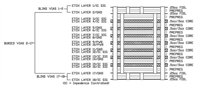
For example, a PCB DFM request that does not state the copper weight for each layer is less than ideal because certain important design rules (such as minimum trace width and spacing) change with copper weight. A design that passes a preliminary DFM check using standard 1-ounce rules may fail later at pre-production checks, when a previously unavailable document reveals that the circuitry was actually designed to use 3-ounce copper. Re-checked against the 3-ounce rules, the spacing turns out to be too tight to manufacture. The order status changes to hold, and the entire circuit needs to be re-routed, using more generous design rules. Worse, the rules make it impossible to route all the required circuitry without adding extra layers, so the PCB cost increases. This is an escalating bad situation for all involved.
While it is possible to run checks with partial information, the checks will be more thorough and conclusive if all the relevant information arrives at the same time as the request for DFM review. A complete file set should include all Gerber layers, all drill files, and all fabrication notes. The notes should list (at least) the material type, the printed circuit board thickness, and copper weights for all layers, as these parameters are essential for setting up accurate checks. Information that is as comprehensive as possible helps to ensure that once you have received your DFM report, you can proceed confidently to production with a minimum of potential for unwelcome last-minute surprises.
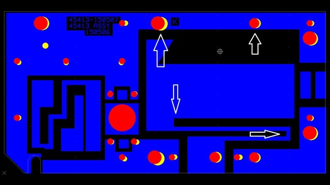
Example of PCB drawing and Gerber data do not agree.
The red above shows all holes in their correct dimensional locations. The yellow shows how far off the holes were, as supplied. There are several feature shape discrepancies between the supplied etch and the drawing, indicated with arrows.
DFM Report Quality
Just as the fabricator’s checks will be completer and more accurate if the incoming data files and notes are as complete as possible, the quality of the DFM report you receive is also important. There is not much point to a report that does not clearly spell out what the analysis has revealed. If it consists of a sprawling, multiple page list of every design rule check that was done, with little explanation of what the violations mean, then it will be of limited use to you in optimizing your design.
Instead of an undifferentiated data dump, you should receive a report with just enough detail with graphics that illustrates problem areas and text that offers suggested remedies. A comprehensible report will enable you to study and then correct reported violations at the CAD design level before you export a new set of files for the manufacturing run.
Updating the CAD is a better approach than letting the fabricator make edits to the Gerber files. It gives you total control of the design. It also ensures that the same problems identified during DFM will not be carried forward to cause problems during a future revision update, or a release to a second source. The purpose of DFM is to remove problems permanently, so whenever time allows, CAD-level corrections are best.

Summary
A combination of automated design rule checks and human analysis adds up to a true DFM review. A complete set of data files and fabrication requirements, sent as early as possible ahead of a planned order, will enable your PCB fabricator to identify issues that may otherwise go overlooked until the point at which they delay production of your order. If your project is a little bit non-standard, DFM is a good first step towards a frictionless manufacturing run.
Key Takeaways
- Design Rule Checks are the foundation: Automated DRCs catch issues like minimum trace width, spacing, annular rings, and missing drills, helping prevent costly scrap, but they only cover process-based rules.
- DFM goes beyond automation: A full DFM review combines automated checks with an engineer’s analysis to identify contradictions in fabrication notes, missing details, or mismatched files that DRCs alone might miss.
- Complete documentation is essential: Submitting all Gerber layers, drill files, and fabrication notes (including copper weight, material type, and thickness) ensures accurate checks and avoids late-stage design changes.
- Report quality impacts outcomes: A useful DFM report highlights problem areas with clear explanations and visuals, offering corrective actions rather than an overwhelming data dump.
- Correcting at the CAD level is best practice: Making updates in your design software, instead of letting the fabricator edit Gerber files, ensures long-term accuracy and prevents recurring issues in future revisions.