Determining the manufacturing process of your design is a key decision that should be addressed at the start of the design stage. The impact of how your design is manufactured will either limit or open up new options for how your idea can be explored.
In terms of how you may look to have your design manufactured, you may want to consider injection molding. Injection molding is used in various medical equipment, hardware and tools, kitchen supplies, and many more everyday items that you may not realize are manufactured by this method. Benefits to choosing injection molding include low cost per part, ease of repeatability, high production output, reduced waste, consistent parts, and much more.
Now that you’ve decided that your product will be injection-molded, there are various design limitations to be aware of when you are ready to bring your idea from the drawing board to real life. Parts must be designed with ease of fabrication in mind; for injection molding, this means how the part will be removed from the mold once cooled. Parameters that affect this include draft angles on the features of your part, keeping a uniform wall thickness throughout your piece, and avoiding any variation of overhang or undercut in your design. While there are certain restrictions to your design, you are also able to expand your design to include specific hardware, surface finishes, and customizable features. Use these guidelines as a way to verify that your design can be successfully injection molded.

Draft Angle and Overhangs
In order to remove the molded plastic properly and safely from the mold, parts are often designed with a draft that helps ensure that surfaces are easily removed without causing damage to the part. The general rule is to have a draft of at least one degree to features where needed. You may need to increase this angle depending on the size of your part and what surface finish you’re looking to achieve. Especially when a specific surface finish is desired, the draft angle is an important factor that needs to be kept in mind.
Steeper angles may make it easier for you to achieve a smoother finish on the outer surface, but only if you are able to accommodate that draft angle. Another parameter to keep in mind while in the design stage is if there are any overhangs to your model. Just including a draft angle to your part is essential to removing your molded piece successfully and avoiding any undercuts or features that can lock onto the mold after cooling. These features will prevent the part from being removed safely and will break off when ejected.
Parting Lines and Ejection Marks
While you may desire to have all surfaces of your molded part smooth and pristine, there are some marks that cannot be completely avoided with the injection process. Parting lines and ejector pin marks are seen on molded parts after the molding process is complete. Parting lines occur where the two halves of a mold meet, most commonly across the middle of a part. Though occasionally seen as only a harmless cosmetic, the location may not always be acceptable.
Parting lines on mating surfaces or areas where visuals are key are less than ideal but can be resolved in a couple of ways. The first is to try to relocate the parting line to the edge of the part so it is less noticeable. This may result in a slight redesign of some features but would help achieve a cleaner finish. Secondary operations may also be used to remove parting lines but would add costs.
Ejector pins help force the finished piece outside of the mold once cooling has been completed. However, these pins leave a circular mark on either the inside or outside surface of your part. Depending on the size of your part, this may leave a very small, almost unnoticeable mark on the piece, or leave a larger circle on bigger designs. Just as for parting lines, the location of the ejector pins can be adjusted so that you may achieve a certain desired surface finish. Be mindful of how your part will look after it is removed from the mold, and what you can do within your design constraints to help meet your desired finish.
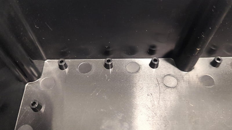
Ejector pin marks left over from the molding process.
Uniform Thickness
With injection molding, it is crucial that the wall thickness of your part falls within the acceptable range denoted by the manufacturer. 2-5 millimeters is the typical thickness range that most pieces can be molded with before any sink marks or any type of failure occurs, but this may vary depending on the type of plastic you are using. It is also essential to keep the wall thickness of your piece uniform, though if sections of different thickness are required, the transition between thicknesses can be done if rounded corners and smooth transitions are utilized. If the difference in thickness needed is small enough, a small recess can be cut into the wall. Ensuring that there are no sharp corners or edges to this cut will help with the removal process. Especially if there is a slide already being used on the side, adding a cut like this will not impact costs.
If there are any bosses that are required within your design, they must also meet the same requirements for wall thickness. While bosses are great for adding inserts to or strengthening your part, if not designed correctly, they will cause your part to fail. For example, if you create a 10mm x 10mm feature that is completely solid, you are bound to see sink marks on the outer faces of the boss. A feature of this size is too thick to retain its shape during the cooling process and must become thinner to retain its overall shape. Hollowing out these features can reduce the wall thickness and become thin enough to avoid any deformation during cooling. If you can follow this practice throughout the design stage of your product, you will see more success with the molding process.
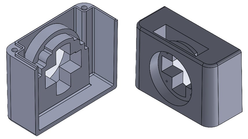
An example of a large boss that is hollowed out to achieve moldability.
Hardware Inclusions
Depending on the product you’re designing, fasteners and other hardware may be required in your build. One of the advantages of injection molding is being able to mold around these kinds of hardware, otherwise known as insert molding.
Insert molding is a great way to reduce labor costs, improve reliability, and make your finished part into a single piece. As the melted plastic surrounds the metal piece when being injected, it forms a cohesive bond around that part to ensure a strong and rigid mate. When you are considering the addition of inserts in your design, it is also important to keep note of the location and type of insert within your design.
Depending on the size and shape of your insert, certain specifications such as the amount of plastic surrounding the part are integral to successfully mold in your part. Screwdrivers and flash drives are both examples of multi-component parts that are assembled into one individual piece during the process of injection molding.
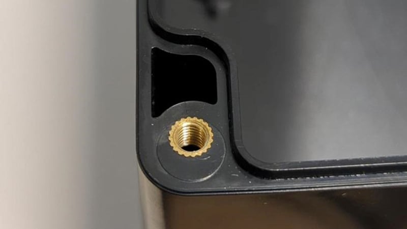
Insert molding example of heat-set threaded inserts.
Customization
Once the physical parameters are determined for your design, the cosmetics and appearance are the last thing you would want to decide upon. Depending on the functionality of your product, certain surfaces may require unique finishes. Perhaps you need one face to be a certain smoothness in order to properly apply a label that’s going to be on the front of your design. Maybe a grittier, rougher finish such as that of sandpaper is needed instead. Either way, there are steps to take to achieve these types of finishes.
As I noted earlier, the draft angle of your part can be altered to help you meet a specific surface finish. The mold itself can be textured to a certain surface classification through the means of polishing, sandpapering, blasting, and more. You are also able to choose the color of the plastic for your design, commonly denoted by a Pantone color. Embossing letters and symbols are a great cost-effective alternative to creating separate labels that you would later add to your part. With only a height of a couple of millimeters, readable text can be added to your piece without risking the product’s moldability.
Summary
With plastics manufacturing becoming more of a viable solution in today’s economy, injection molding is a great step to take to help reduce costs and speed up manufacturing turnaround time. Following these rules above can help ensure design feasibility and save time when bringing your design to a manufacturer. A full-service manufacturing partner like Epec can help perform a thorough review of your design to identify any moldability issues, and high-risk areas, and validate any design variables. Don’t let any overlooked design issues delay you from bringing your exciting new product out to the market.
Key Takeaways
- Draft angles are essential to ensure parts can be safely ejected from the mold, with at least one degree recommended and adjustments made based on size and surface finish requirements.
- Parting lines and ejector pin marks are unavoidable but can be strategically placed or minimized through design choices or secondary operations to maintain cosmetic quality.
- Uniform wall thickness between 2–5 mm prevents defects, while smooth transitions and hollowed features help avoid sink marks or warping during cooling.
- Insert molding enables hardware integration, allowing fasteners and other components to be molded directly into the part for stronger assemblies and reduced labor.
- Surface customization options expand functionality, including textured finishes, color selection, and embossed features that improve both appearance and usability.