


Battery pack manufacturing can be a complex process depending on the size of the pack, the types of battery chemistries used, if a battery management system (BMS) will be used, and whether testing and certification must be done before transportation.
When considering the types of components used in manufacturing battery packs, some of the processes and equipment for the creation of lithium-ion batteries, nickel cadmium batteries and nickel metal hydride batteries are similar. However, there are many considerations to consider, including the battery management system, whether one is necessary for the application, and how the manufacturing of this system may impact lead times.

Battery Pack Manufacturing Components
At the start of the design process, learning about a customer's specifications are essential as it helps our Epec engineers figure out what interconnections, field effect transistors, cell configuration, and the cell assembly to place into the prototype and final battery pack assembly. We need to know more about the application's power requirements, the battery pack's capacity and voltage standards, and thermal management when the battery pack is used in high-powered applications. Based on these requirements, it helps us to use the right components and equipment for a successful production process.
Common components of the manufacturing process include electrode coatings, cell assembly, and material activation, along with designing the BMS components.
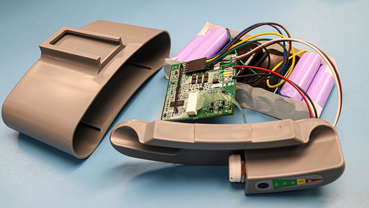
Custom manufactured battery pack for a medical device with various components.
Electrode Coatings
The battery cell's cathodes and anodes will be coated to assist with conducting the current into and out of the battery cells. These coatings may also increase corrosion and oxidation resistance while decreasing contact resistance. The type of coating used will be based on the battery chemistry, such as copper and aluminum, and the coatings come as a powder that is applied. The anodes and cathodes are usually coated separately to prevent contamination.
Cell Assembly
Cell assembly will be dependent on the type of cell configuration that is used: prismatic cells, cylindrical cells, or pouch cells. A stacked electrode sub-assembly will be used with prismatic and pouch cells, as a spiral wound electrode sub-assembly is typically used for cylindrical cells. Then the clamps to connect the electrodes, the electrode stack/jellyroll case, connections, terminals, vents, and safety devices will be added in a specific order before the heat sealing and welding processes take place to seal the case.
The basic assembly for the prismatic and pouch cells when creating lithium-based batteries involves cutting the anodes and cathodes into electrode plates and stacking them in an alternating fashion. These plates are kept apart by using a separator. The basic assembly for cylindrical cells for the same battery chemistry involve cutting the anode and cathode into long strips. These two long stripes and the separator are wrapped around the cylindrical mandrel. A tab is used to connect the electrodes to the terminals.
Material Activation
When manufacturing the battery pack, the materials are inactive until the cell assembly is completed. At this stage, the cell will undergo a single controlled charge and discharge cycle to activate the materials. This process is called formation. The charging process begins at a low voltage that is slowly increased. During this phase, our engineers will collect the necessary performance measurement data, such as the cell capacity and impedance, to perform quality assurance.
Battery Management Systems
Battery management systems, also called battery monitoring, helps to check the performance of the battery to prevent issues. This system will have key performance parameters regarding the required charge and discharge cycles, ambient temperature ranges, and internal temperatures. If the voltages, currents, or temperatures exceed recommended parameters, the BMS may generate an alarm to inform the user of the issue. The BMS may also automatically disconnect the battery from the charger or load to prevent damage to the battery pack or the application.
BMS components may consist of several different internal circuits (ICs). These may consist of backup ICs, charger ICs, source selector ICs, and many others. There will also be several functional blocks. These blocks will have cutoff field effect transmitters (FETs), cell-voltage monitors, real-time clock, cell-voltage balance, temperature monitor, and a fuel gauge monitor.
A BMS is always needed with lithium-based batteries but is not a requirement for nickel-based chemistries. However, it is often recommended to include a BMS with nickel-based chemistries to prevent overcharging as a manufacturer can set a maximum charge voltage as a safety feature.
Integrated Circuits
Integrated circuits, or ICs, will be used based on the application and the size of the battery pack. They typically fall into two categories: generic ICs (analog and microprocessors) and specifically designed ICs (application specific integrated circuits (ASIC) and pre-configured/programmed microprocessors). The ICs that are available are typically used for small battery packs and for large battery packs.
There are lead time considerations when it comes to obtaining ICs for BMS devices. The top factor is availability. Many ICs are only available to larger manufacturers who create large battery packs. For ICs in smaller battery packs, they are available to smaller manufacturers and the public. While these are common and typically inexpensive, demand for these BMS components is significantly increased. This factor places a strain on raw material supplies that are available and can lead to supply shortages when there is high customer demand.
Field Effect Transistors
The field effect transistors provide the connection between the load and the charger and provides isolation. The FETs basically controls the battery pack's current flow and maximum voltage. It uses current measurements and battery-cell voltage measurements, as well as real-time detection circuitry, to keep within specified ranges. There are several different connection figurations that can be used in the BMS based on the type of battery pack modes that are desired. FETs that may be present in the battery BMS include insulated-gate, negative-channel metal oxide semiconductors, and cutoff FETs and DFETs.
Microcontrollers
Microcontrollers help to properly management the information gathered from the sensor circuitry. With the gathered information, the microcontrollers decide on the appropriate course of action to take to control the temperature, voltage, and current. A field programmable gate array may also be used in place of the microcontroller to perform these actions.
Temperature Sensors
Temperature sensors help to monitor the cells to look for thermal spikes that could indicate overcharging or excessive load to the battery pack. Due to the battery chemistries being volatile for lithium-based batteries, a battery can catch fire and/or explode if the temperature reaches an unsafe level. Thermistors will also be used to monitor the circuit's temperatures. To prevent the sensors from obtaining false readings by recording the environmental temperatures, an internal voltage reference is used.
Daisy Chain
A daisy chain is a functional block designed for stacked battery pack BMS designs. It provides a simplified method to circuit connections. This block is often used to replace level-shifting circuitry and optical couplers.
Additional BMS components
Additional components that can be found in a BMS system may include a real-time clock for time stamping activities, memory for data storage, and the battery authentication. The battery authentication is a safety measure placed in by manufacturers to prevent the BMS system from being connected to battery packs that are created by third-party vendors. The BMS system may also have a voltage regulator to power all peripheral circuitry that is around the BMS.
Lead Times and Component Shortages for New Battery Designs
BMS and battery component lead times will vary based on the specific components, raw material availability, and design considerations. Market shortages may happen based on the demand for raw materials, such as cobalt for the creation of nickel-cobalt batteries. Manufacturers are also keeping a close eye on the potential shortages for battery-grade nickel. There may be a looming shortage for nickel sulfate with future demand outpacing capacity in the next few years.
All these factors can increase lead times for battery packs and components that rely on these materials, which may force more manufacturers to switch their operations toward lithium-based battery productions.
Summary
Battery pack manufacturing requires a wide range of components and processes, which vary depending on the chosen chemistry, application, and safety requirements. Core elements include electrode coatings, cell assembly, and material activation, along with critical electronic components like battery management systems, integrated circuits, field effect transistors, microcontrollers, and temperature sensors. The BMS is particularly important for lithium-based batteries, where it ensures safe operation by monitoring and controlling charge, discharge, and thermal conditions. Lead times and supply chain constraints, especially for integrated circuits and raw materials such as cobalt and nickel, can significantly impact development schedules and production capacity.
Key Takeaways
- Electrode coatings and cell assembly form the foundation: Coatings improve conductivity and resistance while cell formats (cylindrical, prismatic, pouch) dictate assembly methods and performance characteristics.
- Battery Management Systems are essential for safety and performance: Especially with lithium-based chemistries, BMS components monitor voltage, current, and temperature while providing protective cutoffs and balance functions.
- Electronic components drive functionality: ICs, FETs, microcontrollers, and daisy chains enable monitoring, control, and safe power delivery, though availability and lead times are major challenges.
- Temperature sensors protect against catastrophic failure: Thermistors and internal references detect thermal spikes to prevent dangerous overheating, fires, or explosions.
- Supply chain risks impact lead times: Raw material shortages (cobalt, nickel, nickel sulfate) and high IC demand can slow new battery designs, pushing manufacturers to adjust timelines or shift chemistries.


